| Engine Assembly,
continued |
56. With the lifters
in place and heads on, we're ready to set the
intake gaskets in place. We're using Fel Pro 1262.
Use a thick RTV bead rather than the cork end
seals. |
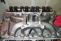
57. The Edelbrock Vic. Jr. intake is carefully
set into place, and intake bolts torqued in sequence
to 18 lb. ft. |
58. If done correctly,
the RTV sealant will form a perfect seal between
the intake and block. |
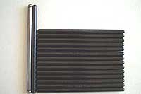
59. Because our
heads have been milled 0.040", the stock
5.0L pushrod length (6.375") was slightly
too long. We ordered a set of Crane 6.250"
hardened pushrods after verifying that length
would yeild optimal roller tip placement. |
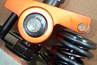
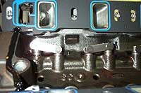
60.
Shown here is ideal roller tip positioning on
the valve stem. The roller wheel should be just
slightly towards the intake side of the valve
stem, when the valve is fully closed. At max lift
the roller wheel will be about dead center. The
objective is to select a pushrod length that minimizes
the "sweep", or movement of the roller
tip or wheel across the valve stem. |
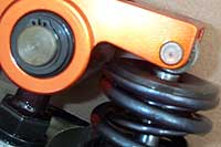
61. With the stock
5.0L pushrod length the roller tip was positioned
close tot he outer edge of the valve stem. As
the valve opens the wheel will travel even further
outward, resulting in excessive preloading of
the valve guide. |
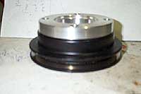
62. Most stroker
kits for the 302 utilize a 28oz balance factor.
As we showed in the part 1 of this series, we
had our flywheel balanced to 28oz. At the front
end we ordered up a 28oz hub for our existing
Fluidamper. The 50oz hub is removed and the 28oz
piece bolts right to the outer ring. |
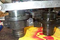
63. One of the
few surprises we encountered with the 331 project
was discovering that the 28oz hub is nearly 1/2"
shorter than the 50oz hub. This is done presumably
to maintain the stock pulley alignment on early
28oz Fords. For us it meant having to order a
custom spacer to work with the single v-groove,
4-bolt pulley we had made specifically for the
50oz hub. |
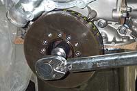
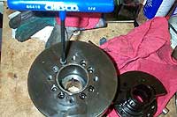
64. If you look
closely you can make out the timing tape we applied
during the previous 302 buildup. This was necessary
because the timing marks on the FLuidamper, when
clocked with a 50oz hub, are intended to match
up to a late-model timing pointer -the kind that
bolts the timing cover, when the waterpump exits
on the right. Well with the 28oz hub we did not
need the timing tape, the scribes on the damper
ring were dead on with the cast timing pointer
on the early timing cover -why? Again we presume
Fluidamper makes the 28oz hub to work with the
early applications. |
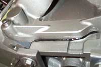
65. Shown is the
Auto Specialties pulley spacer. This will enable
us to line up the crank and waterpump pulleys,
and at $35 it is much cheaper than locating a
set of single groove, four-bolt pulleys (no car
came with such as thing stock as far as we know.) |
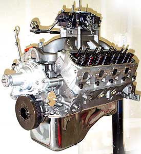 |
There you have it, 331
cubic inches cleverly disguised in a 302 body. As
you have read, building a 302 based stroker is not
drastically different from a proper 302 rebuild. There
are some areas which require added consideration during
the assembly process.
In the next article we'll
discuss the final touches to the induction and exhaust
systems supporting the motor. We'll also have the
motor installed in our '67 Mustang and hopefully bring
you some preliminary track and dyno results.
In the mean time look for some articles on what we're
doing to prepare the '67 for it's new powerplant.
F/M
|