Up until now we haven't discussed
our objectives for the new motor and project car. Project
11.99 was predominantly a strip car. The high-revving
302, equipped with a solid roller cam, was at the outer
edge of streetability, and ultimately became nothing
but a quarter mile machine.
With the 331 we obviously
will have the advantage of torque on our side. We intend
to capitalize on this with a induction system that supports
a broad torque curve from idle to 6000, as opposed to
a steep horsepower curve higher in the rpm range. This
will facilitate great streetability and, we speculate,
maintain about the same quarter mile performance.
To achieve this goal of streetability with high 11-second
performance, we came up with some custom cam specifications.
We'll be running a Crane hydraulic roller with 226 degrees
intake duration and 230 degrees on the exhaust side.
Lift will be 0.542" / 0.552" respectively.
We worked with Crane to design these specs in order
to fully maximize the flow potential of our Total
Engine Airflow ported World Jr. aluminum heads.
[View
Cam Card]
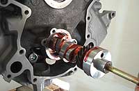
13. We
like to begin assembly by first installing the cam.
It's much easier to guide the cam in without the
crank in the way. |
14. Since this is
a roller cam, we technically don't need more than
some oil on the lobes. We used the supplied cam
lube for good measure anyway. |
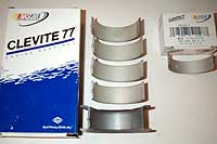
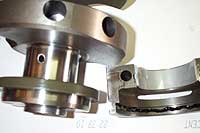
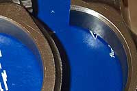
15. With the cam in,
we installed the main bearings and crank. We're
going with Clevite 77 bearings throughout. |
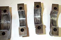
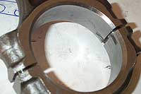
16. Only put moly
on the crank journal side of the bearing. The smooth
bearings go in the caps, the grooved ones go in
the block saddle. |
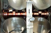
17. Our SCAT crank
uses the late model one-piece rear main seal. Slip
in on the crank, with the open side facing inside
the motor. A thin bead of RTV is used on the seal
surface of the rear main cap. |
18. The crank is carefully
laid into place, followed by the main caps. Use
ARP lube or moly on the stud threads and install
the nuts and washers. |

19. Tighten up the
main caps evenly, then use a torque wrench and torque
in steps from 40 to 80 lb.ft. (follow ARP instructions
depending on the lube you used). Torque from the
center cap, alternating outward. |
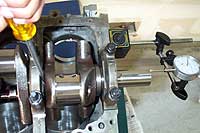
20.
After torquing
the main caps, check for thrust bearing clearance.
Attach a dial indicator against the crank snout,
and use a long screwdriver to pry the crank forward
and backward. Read the total end play, 0.004"-0.0010"
is desired. If less, remove the thrust bearing and
lightly sand the sides and recheck. |
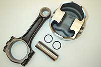
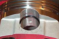
21. With the crank
in place, we turn to assembling the piston and rods.
Because our SCAT kit uses JE pistons with full floating
pins, we can assemble it without the aid of a machine
shop. |
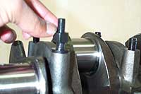
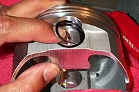
22. While it may appear
the rods are symmetrical on each side, they are
NOT! The large end has two different bevel cuts.
The larger radius rids the outer edge of the crank
journal (crank has a corresponding "filet"
radius.) |
23. This side of the
rod, with the larger radius, rides the filet radius
edge of the crank-rod journal. If it is installed
the other way around the crank will not turn and
major damage will ensue. A rule of thumb: When looking
at the piston as it would sit in a motor (fly cuts
at the top or "up"), the radius side of
the rod will always be on the right. |
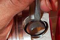
24. Welcome to the
art of installing Spirolocks! Prepare for an hour
of extreme frustration. Actually they are tough
at first but not too bad once you get the handle
of it. Start with splitting the lock with your pointer
finger as shown. Then feed one end into the groove
in the piston. |
|
25. Once you get
one end of the Spirolock started in the groove,
use a small blade screwdriver and holding it straight
up and down to apply pressure on the lock. Gently
apply pressure and rotate your wrist so the blademoves
along the lock, feeding it into the grove.
27. Install one spiral in each piston.
Then using a little oil, install all the pins
and rods. Then go back and install the lock on
the other side of each piston/rod combo. Finally,
check to make sure all the locks are securely
in their grooves.
|
26. Once you get the hang of the screwdriver
technique the locks will go in in a matter of seconds.
But until then, keep at it, and don't worry if you
mess a lock up...they usually give you a bunch of
extras. Remember, there is NO WAY to squeeze the
lock ring together to make it fit the hole...so
don't even bother. It must be fed in end to end. |
|
|
|