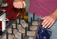
 With the main cap bolt holes clear of machining debris,
we installed ARP studs just a pinch more than finger tight.
With the main cap bolt holes clear of machining debris,
we installed ARP studs just a pinch more than finger tight. |
|
 The main saddles were wiped clean with brake cleaner and
lint-free towels.
The main saddles were wiped clean with brake cleaner and
lint-free towels. |
| |
|
|
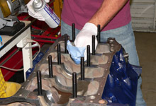
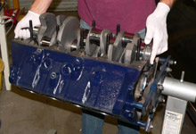
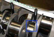
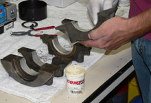
 Here we are installing the "block-side" Clevite
77 main bearings. The "block-side" main bearing
halves incorporate an oiling groove. The grooved thrust
bearing goes on journal number three.
Here we are installing the "block-side" Clevite
77 main bearings. The "block-side" main bearing
halves incorporate an oiling groove. The grooved thrust
bearing goes on journal number three. |
|
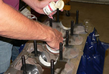
 We used lithium based Comp
Cams Engine Assembly Lube to coat the main bearings
once they were installed.
We used lithium based Comp
Cams Engine Assembly Lube to coat the main bearings
once they were installed. |
| |
|
|
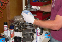
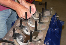
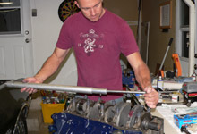
 Once wiped down, the crank was ready ride the saddles.
 |
|
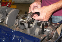
 The crank was carefully set in place with caution to avoid
bumping a journal on a main stud.
The crank was carefully set in place with caution to avoid
bumping a journal on a main stud. |
| |
|
|
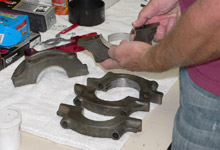
 After wiping down the main caps, we set the other half
of the main bearings into place. No oil or assembly lube
required here.
After wiping down the main caps, we set the other half
of the main bearings into place. No oil or assembly lube
required here. |
|
 Now was the right time to check main bearing clearance,
therefore no assembly lube was applied to the crank side
of the bearing surfaces yet.
Now was the right time to check main bearing clearance,
therefore no assembly lube was applied to the crank side
of the bearing surfaces yet. |
| |
|
|
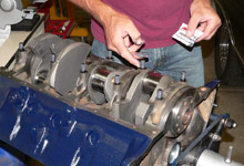
 We used "Green" Plastigauge and set a length
across one of the main journals. "Green" Plastigauge
is for measurements between 0.001" and 0.003"
inch - typical engine bearing clearances.
We used "Green" Plastigauge and set a length
across one of the main journals. "Green" Plastigauge
is for measurements between 0.001" and 0.003"
inch - typical engine bearing clearances. |
|
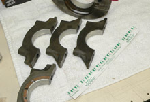
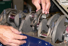
 We proceeded to install all five main caps. The thrust
main bearing and cap goes on journal number three.
We proceeded to install all five main caps. The thrust
main bearing and cap goes on journal number three. |
| |
|
|
 ARP hardware requires the use of the included ARP moly.
We applied some to the threads of each stud.
ARP hardware requires the use of the included ARP moly.
We applied some to the threads of each stud. |
|
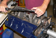
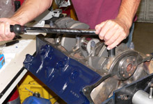
 The caps were installed in an alternating sequence to
90 ft lbs. Once torqued down, the main caps were ready
for removal.
The caps were installed in an alternating sequence to
90 ft lbs. Once torqued down, the main caps were ready
for removal. |
| |
|
|
 Don't use a torque wrench to remove anything. Here, we're
using a long breaker bar to break the nuts free of the
main studs.
Don't use a torque wrench to remove anything. Here, we're
using a long breaker bar to break the nuts free of the
main studs. |
|
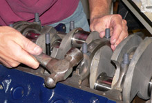
 Some light upward tapping with a hammer helps dislodge
the main caps.
Some light upward tapping with a hammer helps dislodge
the main caps. |
| |
|
|
 We carefully lift the main cap to expose the journal where
the Plastigauge was applied.
We carefully lift the main cap to expose the journal where
the Plastigauge was applied. |
|
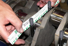
 The Plastigauge indicated a main bearing to crankshaft
clearance of between .0015" and .002". The allowable
range for the Ford 400 is .0009" and .0026".
Success!
The Plastigauge indicated a main bearing to crankshaft
clearance of between .0015" and .002". The allowable
range for the Ford 400 is .0009" and .0026".
Success! |
| |
|
|
 With the main bearing clearance confirmed as allowable,
we wiped the main bearings and caps clean, reinstalled
them and applied some assembly lube the "crank-side"
surfaces.
With the main bearing clearance confirmed as allowable,
we wiped the main bearings and caps clean, reinstalled
them and applied some assembly lube the "crank-side"
surfaces. |
|
 The main caps were then reinstalled and torqued once again.
To reemphasize, this was not our final installation of
the crankshaft for this build.
The main caps were then reinstalled and torqued once again.
To reemphasize, this was not our final installation of
the crankshaft for this build. |


