 |
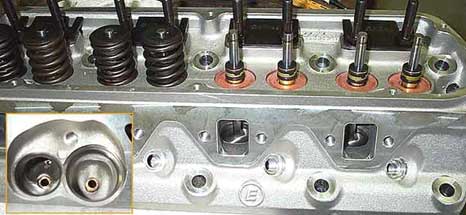
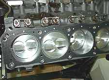
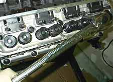
The Edelbrock Performer heads (part
no. 6037 shown) are well crafted and come pretty much
ready to go out of the box. The 1.90" / 1.60"
valves and 60cc chambers ought to work well with our Lunati
51023 camshaft (even though Edelbrock would scoff at the
idea of using a Holley product rather than their own.)
|
Head and Valvetrain
Modifications
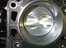
As we mentioned earlier,
we were amazed to find that Edelbrock does not use a spring
cup, or at least hardened shims, to prevent the valve
springs from damaging the soft aluminum. The photo above
shows the soft copper alloy shims that were included with
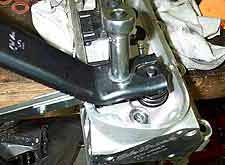
the heads. Such shims should not be used on a performance
engine at all, since they cannot tolerate the spring pressures,
high rpm, and the hard tool steel spring damper found
in most valve springs.
The solution was to disassemble heads and have a local
machine shop cut the spring pockets to accommodate a 1.550"
diameter hardened spring cup as shown. Edelbrock actually
recognizes this problem and if you call their warranty
department, they will supply you with the spring cups
for no charge. However it did cost us $80 at our local
machine shop for the labor.
Beware that the cutting process for the new hardened seats
requires slightly deepening the spring pocket in the head.
This means that when you reinstall the valve springs,
they are likely not to be at the same installed height
as before. (Installed height is the distance between the
spring seat (including and shims) to the underside of
the retainer.) Installed height is what determines spring
pressure, and spring pressure is what keeps the valves
closed. Be certain to check the installed height and if
needed install shims below the spring cups to get the
installed height within the spring manufacturers specifications.
In our case we needed about .040" worth of shims
below the 0.060" thick hardened spring cup to get
to the 1.800" installed height required to achieve
130 lb. of pressure recommended for our camshaft. You
should always place the shims below the hardened cup on
an aluminum head. On an iron head you do not need a spring
cup, but should always use a hardened tool-steel shim.
Because we would be running a cam with more lift than
stock, we decided to replace the stock Edelbrock springs
with a higher rate, dual valve spring. We had a set of
Comp Cams 987-16 springs laying around the shop which
turned out to match our cam and heads perfectly. They
measure 1.440" O.D., and have a seat pressure of
130 lbs. at an installed height of 1.800", and an
open pressure of 325 lbs. at 1.250". This is about
20 lbs. more than recommended for our camshaft, however
because springs lose 5-10% of their rate after the initial
heat cycle, we were not concerned. Note however that excessively
stiff springs not only rob horsepower due to the increased
friction, but they also increase wear on the cam and lifters.
In our opinion single valve springs, as supplied with
the Edelbrock Performer heads, are not a good idea for
use with a roller cam. Research by Crane and other camshaft
companies has shown that steel roller cams create very
harsh valve train harmonics that stress valve springs
far more than flat-tappet camshafts. Dual valve springs
are much better at distributing this harmonic load, and
thus most cam manufacturers will list a dual spring for
even their mildest hydraulic roller cam. |
Assembly |
|
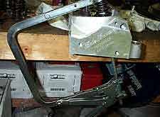
13.
There are several tools available for removing and
installing valve springs. Our experience is that
you'll need all of these tools to do the job! Shown
here is a large 'C' clamp device which compresses
the valve spring while supporting the valve. This
tool can only be used with the head off the motor. |
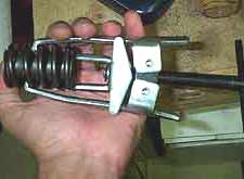
14.
The handheld spring compressor shown works well
for removing springs while the heads are on the
motor. However with dual springs, or stiffer spring
rates, the tool tends to slip off the coil. Wear
safety glasses when compressing valve springs! |
15.
The lever style tool also is designed to be used
with the heads on the motor, but only works on a
stud mount head. It attaches to the stud and then
forces the spring down. With all these tools you
will need to give the retainer a smack with a hammer
to free up the keepers. |
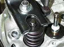
16.
In this
photo we're using both the C-clamp tool and the
level tool to install the Comp Cams 987-16 springs.
The Edelbrock retainers and locks fit the new springs
perfectly.
We first use the C-clamp compressor to put some
tension on the spring and keep the valve in place.
Then with the C-clamp locked in placed, the lever
tool is placed over the stud and a ratchet used
to tighten the lever, which compressed the spring.
Once the spring is compressed below the keeper groves
on the valve stem, the locks are carefully placed
in and the then the lever is backed off and C-clamp
removed. |
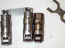
17.
Before putting the heads on, we installed the hydraulic
roller lifters. Even though roller lifters can be
reused (assuming the roller is in good shape) we
decided to buy new lifters since ours were stock
with over 140K miles.
Unfortunately Crane was backordered on their stock
replacement lifters, and since we were in a rush
we went with their vertical link-bar lifter (left).
The linkbar lifter (Crane part no. 36532-16) is
actually the same dimensions as a stock lifter,
but utilizes a link bar between two lifters, rather
than a "dog bone" to keep the lifter from
spinning in its bore. |
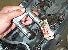
18.
The nice thing about the Crane linkbar lifters is
that they eliminate the need for the stock lifter
retainers. Simply apply some moly or cam lube and
drop them in their bores, with the linkbar facing
the center of the block, as shown.
The only downside to the Crane linkbar lifters is
they cannot be installed with the heads on the block,
due to the taller design. We installed ours before
bolting down the heads.
The Crane linkbar lifter can actually be used to
convert non-roller blocks to accept a roller cam,
since they do not have the proper machine work to
utilize the stock roller lifter retainers . |
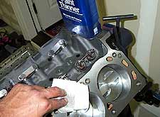
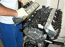
19.
With the lifters installed, we were ready to bolt
down the heads. Clean the surface of the block and
heads thoroughly with a degreaser or paint thinner.
|
20.
We're using a Victor Reinz 3428 stock replacement
head gasket -nothing fancy, about $14 a piece. It
has an iron fire ring, and a graphite reinforced
body. It seals aluminum heads to an iron block flawlessly,
and will last 100K without any trouble.
Install the gaskets without any sealant, and with
the words "FRONT" at the front of the
block -even if it means FRONT is upside down on
oneside. |
21.
If you have small-block Ford head gaskets without
FRONT stamped in them, position the gasket so the
water passages in the rear of the block are open
(as shown.) The passages in the front of the engine
are blocked by the gasket, as shown in the previous
photo.
Always use the alignment dowels,
two on each side of the block!
|
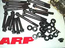
22.
Perhaps the most critical part to proper head gasket
sealing is using quality fasteners. Late model 5.0L
factory headbolts should not be reused because they
use a TTY (torque-to-yeild) procedure for torquing
the bolt. We recommend a set of ARP headbolts. Not
only are they stronger than stock, but they are
installed using a standard lb.ft. torque wrench.
We also needed some 1/2" to 7/16" ARP
bushings because Edelbrock heads come drilled for
1/2" head bolts for use on 351W engines. 289/302/5.0L
engines use a 7/16" headbolt. |
23.
With the gaskets correctly oriented, and the dowels
in place, the heads are set onto the shortlblock.
Install the longer, upper, head bolts with a little
bit of ARP moly on the threads and under the head
of the bolt. The lower head bolts need silicone
sealer on the threads since the pass through the
coolant passages. |
24.
It is important to follow the prope torquing sequence
for head bolts, especially with aluminum heads,
otherwise you risk warping a head and a blown head
gasket. Start by first tigthening each bolt just
hand tight. Then begin with the upper center head
bolt and torque it to 20 lb.ft., followed by the
lower center, then work your way outwards, alternating
to each side of center. Once they are all torqued
to 20 lb.ft., repeat the procedure at 50 lb.ft.,
then 80 lb.ft. (Some shop manuals suggest torquing
the upper head bolts to 80 lb.ft. and the lowers
to 70 lb.ft. To avoid confusion, we torque them
all the same.) |
| |
|
 (Assembly
continued.) (Assembly
continued.) |
|
|
|
|
|
|
|
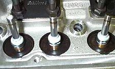
Along with having the Edelbrock heads
modified for hardened spring cups, we also upgraded to the
white Teflon type valve stem seals shown, rather than the
rubber ones that are supplied with the Edelbrock heads (top.)
The Teflon seals do a much better job of sealing, but more
importantly they do not become brittle and break apart with
exposure to head - a problem with the rubber seals. Furthermore
the thicker rubber seals may interfere with dual valve springs. |
|


