|
The Twist on
Swirl
 Since
the Cleveland flow data we gathered for this article included
thought-provoking swirl data and because "swirl"
is a term you'll see tossed around internet forums and magazine
pages, we thought we'd research the mysterious "twist".
In doing so, FordMuscle opened the proverbial "can-of-worms"
in trying to define the advantages and disadvantages of swirl
by consulting various industry professionals like Rick Roberts
from Edelbrock, Tony Mamo from Air Flow Research, Joe Sherman
of Joe Sherman Racing Engines, and John Yelich from CHW. We
also scoured our own reference materials and even referred
to a UC Irvine study on the subject from their Department
of Mechanical and Aerospace Engineering (see second sidebar
below). Here's what we found. Since
the Cleveland flow data we gathered for this article included
thought-provoking swirl data and because "swirl"
is a term you'll see tossed around internet forums and magazine
pages, we thought we'd research the mysterious "twist".
In doing so, FordMuscle opened the proverbial "can-of-worms"
in trying to define the advantages and disadvantages of swirl
by consulting various industry professionals like Rick Roberts
from Edelbrock, Tony Mamo from Air Flow Research, Joe Sherman
of Joe Sherman Racing Engines, and John Yelich from CHW. We
also scoured our own reference materials and even referred
to a UC Irvine study on the subject from their Department
of Mechanical and Aerospace Engineering (see second sidebar
below). Here's what we found.
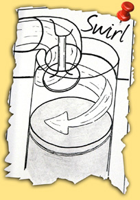
By definition, swirl is the term for the corkscrew movement
of an air-fuel mixture down the last few inches of the intake
runner and into the cylinder, similar to the vortex you see
when the last few gallons of water drain out of your bath
tub. For those cylinder heads that do exhibit a swirl effect,
the point at which a swirl is initiated based on valve lift
can show great variation as you'll see with our subject Cleveland
heads.
The
illustration above showing an air-fuel path around the intake
valve and into the combustion chamber is really the best way
to visualize the phenomenon of swirl. Albeit, this image is
greatly simplified for the purpose of gaining a quick understanding.
The movement seems clear, looks powerful, and at first glance
you might be inclined to say... Why that's gotta be the optimum
intake charge for any head!
 Unfortunately, for the enthusiast, there are a few lines of
thought in the professional realm as it relates to swirl and
whether it should be chased after, chased away, or politely
ignored. These attitudes prevail within original cylinder
head design as well as with engine builders and head porters.
With that aside, the common opinion among professionals is
that swirl is an important factor in atomization and combustion
efficiency, although research on swirl specifically (as opposed
to broader subject of turbulent flow) has not
provided a foundation for which to draw any hard and fast
conclusions.
Unfortunately, for the enthusiast, there are a few lines of
thought in the professional realm as it relates to swirl and
whether it should be chased after, chased away, or politely
ignored. These attitudes prevail within original cylinder
head design as well as with engine builders and head porters.
With that aside, the common opinion among professionals is
that swirl is an important factor in atomization and combustion
efficiency, although research on swirl specifically (as opposed
to broader subject of turbulent flow) has not
provided a foundation for which to draw any hard and fast
conclusions.
Regardless, we've simplified two
common positions on swirl that you might come across. Let
us warn you that after reading the positions you'll still
be forced to draw your own conclusions regarding what remains
a quiet controversy. And while our three Cleveland head's
flow data show interesting variations in swirl behavior, the
only real test would be to throw each head on one motor designed
for a specific application and dyno test the different combos.
 Common Argument for Promoting Swirl
Swirl increases the mixing of fuel and air by diffusing the
mixture to the
swirl path's centerline by forming a recirculation zone. Swirl
increases
combustion efficiency through increased atomization. (See
sidebar "UC Irvine Mechanical and Aerospace Engineering
Studies Combustion Enhancement Using Induced Swirl").
Common Argument for Eliminating Swirl
Swirl decreases the mixing of fuel and air by "flinging"
fuel particles
out of suspension in a centrifugal effect. Too create swirl
an intake
runner must be shaped to promote the effect. Swirl promoting
"shapes" in the form of unique intake contours or
turns will impede an intake charge's rate of flow.
 Keep
the two positions above in mind next time you see the term
"swirl" used by a peer, a manufacturer, or even
included on your own cylinder head's flow chart. According
to Rick Roberts, Edelbrock's Director of Engineering, a more
accurate way of rating the performance of an intake or exhaust
runner is to measure the head's flow coefficiency. Flow Coefficient
or the relationship between the pressure drop across an orifice
and the corresponding flow rate (Static Pressure and Velocity)
provides us with measurable, dependable, and relevant scientific
results. Swirl is just one aspect that can affect the Flow
Coefficient.. Keep
the two positions above in mind next time you see the term
"swirl" used by a peer, a manufacturer, or even
included on your own cylinder head's flow chart. According
to Rick Roberts, Edelbrock's Director of Engineering, a more
accurate way of rating the performance of an intake or exhaust
runner is to measure the head's flow coefficiency. Flow Coefficient
or the relationship between the pressure drop across an orifice
and the corresponding flow rate (Static Pressure and Velocity)
provides us with measurable, dependable, and relevant scientific
results. Swirl is just one aspect that can affect the Flow
Coefficient..
Just show
me the Cleveland flow numbers please!
| |
 |
Turbulent Flow and Swirl
The term "swirl" fits into the broader and more
comprehensive category of turbulent flow. To express the
swirling action of the pesticide stream coming off the
tip of this crop duster in RPMs alone may be a bit short-sighted. |
| |
A Look Beyond Swirl
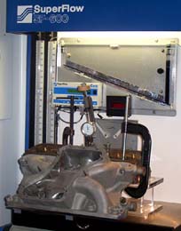
While a swirl meter integrated
into a flowbench can provide a reference point by which to
rank an intake runner's ability to set a charge into motion,
a swirl meter does not fully express turbulent flow (see "Rendering
2" below and "Turbulent Flow and Swirl" at
right). To simplify the comparison of swirl to turbulent flow,
cylinder heads with identical swirl readings from a flow bench's
swirl meter can have different behavior within the runner.
By behavior we are referring to an array of high and low static
pressure areas and the related high and low velocity areas.
Therefore, to only address swirl is to only look at a small
part of a more complex picture of turbulent flow.
What this all really means
to the enthusiast staring at cylinder head swirl data is that
swirl defies the assignment of a set of hard and fast target
numbers for optimum performance. Edelbrock's, Rick Roberts
supplied these 3D renderings as an indication of just how
much action is really going on within a cylinder head. Clearly
it would take an entire education in Fluid Dynamics to intelligently
study these renderings, however it doesn't take much see that
static pressure and velocity take precedent over swirl at
this level of intake runner development.
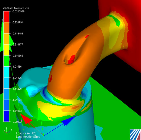
Rendering
1: Static Pressure Within an Intake Runner
There is an inverse relationship between static pressure and
airflow. As static pressure increases, airflow drops. For
example, note the red "hotspot" around the valve
guide boss below. That area represents a high static pressure
point which correlates with low velocity.
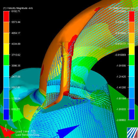
Rendering
2: Static Pressure and Velocity Within an Intake Runner
Note arrows that indicate
airflow velocity and direction. 3D renderings like this one
are use by Edelbrock to evaluate turbulent flow.
 (Flow
and Swirl Testing) (Flow
and Swirl Testing)
|