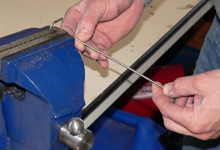
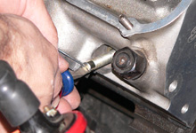
 We made up a pointer. The last twelve inches of a spare
Ford antenna made for some good material. It was worked
out in a vise. We made up a pointer. The last twelve inches of a spare
Ford antenna made for some good material. It was worked
out in a vise. |
|
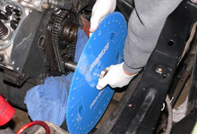
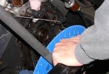
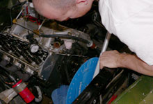
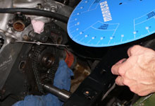
 As shown in the sidebar, we popped this large Moroso degree
wheel onto the crankshaft and loosely attached the knurled
adjustment nut. As shown in the sidebar, we popped this large Moroso degree
wheel onto the crankshaft and loosely attached the knurled
adjustment nut. |
| |
|
|
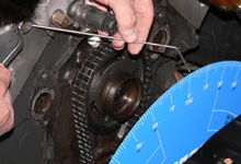
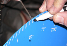
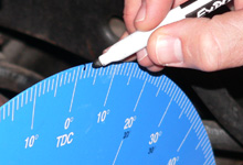
 With the crank in the same estimated TDC position as shown
in caption 2 of "Visual Inspection" on page
1, we secured the pointer and adjusted the degree wheel
to zero. It was OK that the crank position was just a
rough estimate of TDC. With the crank in the same estimated TDC position as shown
in caption 2 of "Visual Inspection" on page
1, we secured the pointer and adjusted the degree wheel
to zero. It was OK that the crank position was just a
rough estimate of TDC.
|
|
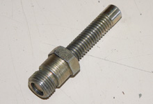
 Here's one of those specialized cam degreeing tools, the
piston stop. Here's one of those specialized cam degreeing tools, the
piston stop. |
| |
|
|
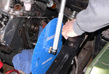
 After rotating the motor 15-20 degrees counterclockwise,
we installed the stop until it just touched the top of
the number one piston. After rotating the motor 15-20 degrees counterclockwise,
we installed the stop until it just touched the top of
the number one piston. |
|
 We continued to rotate the engine counterclockwise until
the number one piston contacted the stop as the piston
returned up the bore. We continued to rotate the engine counterclockwise until
the number one piston contacted the stop as the piston
returned up the bore. |
| |
|
|
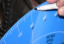
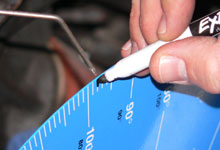
 At this point, we marked the degree wheel. In this case
it stopped at 19.5 degrees After Top Dead Center (ATDC). At this point, we marked the degree wheel. In this case
it stopped at 19.5 degrees After Top Dead Center (ATDC). |
|
 Next, we rotated the crank the other direction, clockwise. Next, we rotated the crank the other direction, clockwise. |
| |
|
|
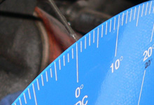
 Once the piston contacted the stop, we marked the degree
wheel again. This time it stopped at 22 degrees Before
Top Dead Center (BTDC). Once the piston contacted the stop, we marked the degree
wheel again. This time it stopped at 22 degrees Before
Top Dead Center (BTDC). |
|
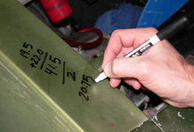
 Absolute Top Dead Center was half way between 19.5 degrees
ATDC and 22 degrees BTDC. Doing the math, we simply needed
to rotate the crank 20.75 degrees clockwise. Absolute Top Dead Center was half way between 19.5 degrees
ATDC and 22 degrees BTDC. Doing the math, we simply needed
to rotate the crank 20.75 degrees clockwise. |
 We removed the piston stop and marked the degree wheel
20.75 degrees to the left of 22 degrees BTDC. We removed the piston stop and marked the degree wheel
20.75 degrees to the left of 22 degrees BTDC. |
|
 Turing the crank clockwise, we reached the midway point
and loosened the degree wheel and resecured it at zero.
The number one piston was now at absolute Top Dead Center. Turing the crank clockwise, we reached the midway point
and loosened the degree wheel and resecured it at zero.
The number one piston was now at absolute Top Dead Center. |
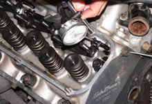
With the number one piston at absolute TDC, we set up
a dial indicator on the intake valve pushrod of the same
cylinder. We rotated the engine clockwise. When the needle
on the dial indicator changed direction we had reached
maximum lift. The dial was set to zero at this point. |
|
Next, we rotated the motor counterclockwise until the
dial indicator read roughly .100". At that point
we then reversed direction and rotated the motor clockwise. |
| |
|
|
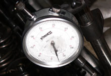
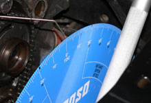
We stopped rotating the motor when the dial indicator
read .050" on the opening side of maximum lift. |
|
The degree wheel was marked at the this point. 98 degrees. |
| |
|
|
We continued to rotate the motor clockwise until the dial
indicator reached zero and read .050" on the closing
side of maximum lift.
|
|
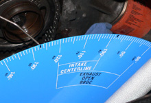
Another mark was placed on the degree wheel at this point.
127 degrees. |
| |
|
|
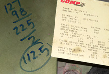
By adding adding the two readings together and dividing
by two, we came to an intake centerline of 112.5 degrees.
Considering the cam card specifies the cam to be installed
at 106 degrees, we were about 7 degrees retarded. |
|
Before going any further or making any timing chain adjustments,
we turned the crank back to absolute Top Dead Center. |
| |
|
|
Next, we removed the degree wheel to begin the process
of checking the intake centerline with the cam gear rotated
clockwise by one tooth. |
|
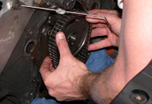
Here we are reinstalling the cam gear one tooth over. |
| |
|
|
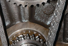
The marks still refused to lineup, but this was the recommended
"early" 429/460 timing chain set. To rule out
any unknown variable we verified the intake centerline
with the cam gear in the new position. We used the same
method shown in captions 1 through 7. |
|
And here is the result. One tooth over on the cam gear
gave us a 97 degree intake centerline. Way too advanced!
It was time to do some serious research. |
| |
|
|
 (429
and 460 Crank Gears, Streetwise 460: Remedy) (429
and 460 Crank Gears, Streetwise 460: Remedy) |
| |
|
|


