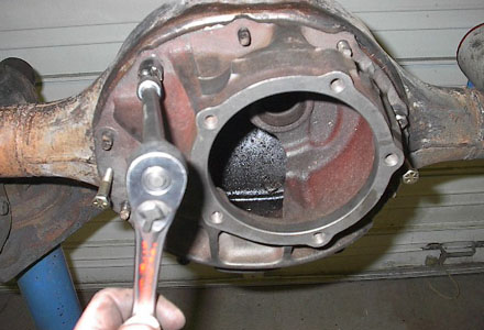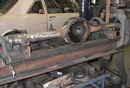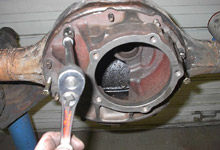
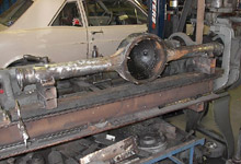
 We bolted the dummy centersection back into the housing
and the alignment bar was slid into place.
We bolted the dummy centersection back into the housing
and the alignment bar was slid into place. |
|
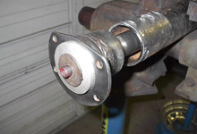
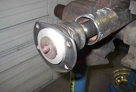
 A small bearing mandrel was tapped into place in the housing
end and it was bolted to the alignment bar. This mandrel
would keep the housing end from moving when it was eventually
welded to the housing.
A small bearing mandrel was tapped into place in the housing
end and it was bolted to the alignment bar. This mandrel
would keep the housing end from moving when it was eventually
welded to the housing. |
| |
|
|
|
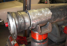
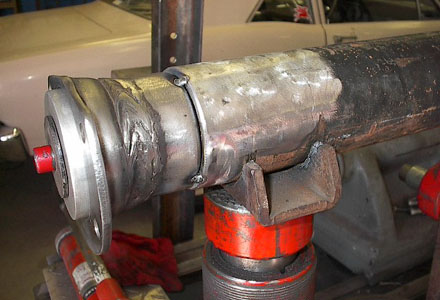
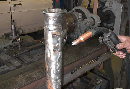
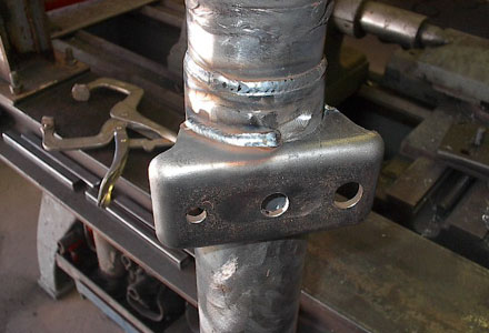
 The housing end was tack welded to the housing in four
places 90 degrees apart before welding.
The housing end was tack welded to the housing in four
places 90 degrees apart before welding.
|
|
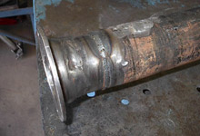
 The housing end was then welded all the way around.
 |
| |
|
|
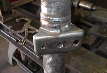
 The spring perches we previously cut off from the 8"
housing were cleaned up with a 4-1/2" angle grinder
to prep them for welding to the 9-inch housing.
The spring perches we previously cut off from the 8"
housing were cleaned up with a 4-1/2" angle grinder
to prep them for welding to the 9-inch housing.
|
|

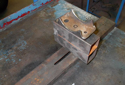
 This is the spring perch fixture that was used to weld
the perches to the housing in the correct location. The
60" x 3" piece of channel iron has slots milled
into it that allow the perch blocks to be adjusted to
the correct spring perch center to center distance. The
blocks have locating pins that allow the spring perch
to sit on them while welding. The spring perch center
to center distance for 1965-1970 Mustangs is 42-3/4".
This is the spring perch fixture that was used to weld
the perches to the housing in the correct location. The
60" x 3" piece of channel iron has slots milled
into it that allow the perch blocks to be adjusted to
the correct spring perch center to center distance. The
blocks have locating pins that allow the spring perch
to sit on them while welding. The spring perch center
to center distance for 1965-1970 Mustangs is 42-3/4".
|
| |
|
|
 The spring perch fixture was clamped to a level work table.
The spring perches were set on the perch blocks and the
housing was set on top of the perches.
The spring perch fixture was clamped to a level work table.
The spring perches were set on the perch blocks and the
housing was set on top of the perches.
|
|

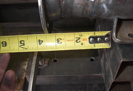
 The housing was centered on the jig, measuring from the
edge of the spring perch to the outside edge of the housing.
The distance on this housing was 3-1/2" on each side.
The housing was centered on the jig, measuring from the
edge of the spring perch to the outside edge of the housing.
The distance on this housing was 3-1/2" on each side. |
| |
|
|
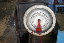
 With the housing centered on the fixture, the housing
was rotated up to 5 degrees on the magnetic base dial
indicator. 5 degrees up is the stock angle for a leaf
spring equipped Mustang, Falcon, Cougar etc. A drag race
application would be slightly less at 2-3 degrees up.
With the housing centered on the fixture, the housing
was rotated up to 5 degrees on the magnetic base dial
indicator. 5 degrees up is the stock angle for a leaf
spring equipped Mustang, Falcon, Cougar etc. A drag race
application would be slightly less at 2-3 degrees up. |
|
 The spring perches were tack welded in four places before
welding.
The spring perches were tack welded in four places before
welding.
|
| |
|
|
 The perches were welded on each side of the perch only
half way before stopping. The same thing was done on the
opposite side of the housing until all the welds were
complete. This was done to prevent too much heat from
being concentrated in one area, which can warp the housing.
The perches were welded on each side of the perch only
half way before stopping. The same thing was done on the
opposite side of the housing until all the welds were
complete. This was done to prevent too much heat from
being concentrated in one area, which can warp the housing.
|
|
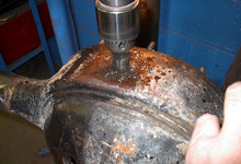
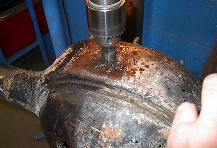
 Next, we began installation of a drain bung that would
allow easier draining of the oil for future gear changes
or maintenance. The bottom of the housing was marked and
drilled with a uni-bit to a diameter of 1".
Next, we began installation of a drain bung that would
allow easier draining of the oil for future gear changes
or maintenance. The bottom of the housing was marked and
drilled with a uni-bit to a diameter of 1". |
| |
|
|
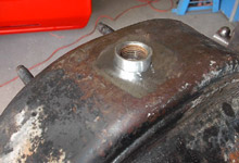
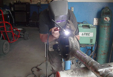
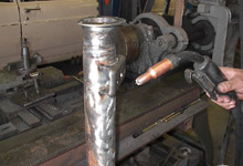
 A 1" diameter 3/8-NPT steel pipe coupling was cut
in half and tapped into the hole. This is a common coupling
that can be bought at any hardware store. A 3/8"
allen head plug will thread into the bung.
A 1" diameter 3/8-NPT steel pipe coupling was cut
in half and tapped into the hole. This is a common coupling
that can be bought at any hardware store. A 3/8"
allen head plug will thread into the bung. |
|
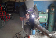
 The bung was TIG welded in place.
 |
| |
|
|
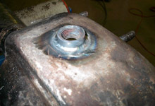
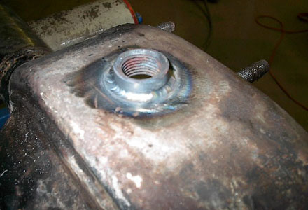
 Here's a close-up of the bung.
|
|
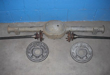
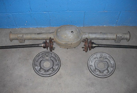
 The housing received a trip to the sandblaster and a thorough
steam cleaning. We used the 28 spline Granada axles in
place of the wimpy 1965 Mustang style axles that taper
down after the bearing journal. The brake shoes, drums,
wheel cylinders, axle bearings, and axle seals are all
commonly available 1975-1979 Granada parts. Powder coating
or painting then assembly were all that were needed to
install the unit in the car.
The housing received a trip to the sandblaster and a thorough
steam cleaning. We used the 28 spline Granada axles in
place of the wimpy 1965 Mustang style axles that taper
down after the bearing journal. The brake shoes, drums,
wheel cylinders, axle bearings, and axle seals are all
commonly available 1975-1979 Granada parts. Powder coating
or painting then assembly were all that were needed to
install the unit in the car. 
|
If you have any questions about the steps
Tom Zuloaga performed in this article please feel free to
contact him directly by email.