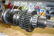
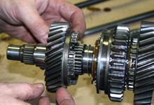
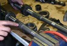
 The output shaft assembly consists of the 1st through
5th and reverse gears as marked. 4th gear is 1:1 locking
of the input and output shafts.
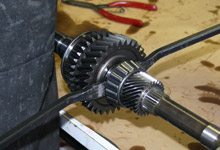
The output shaft assembly consists of the 1st through
5th and reverse gears as marked. 4th gear is 1:1 locking
of the input and output shafts. |
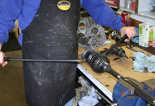
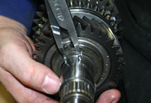
 Bruce recommends mounting the the output, or "main",
shaft in a vice for disassembly. Clamp in the section
shown and not on the splines. A pair of pry bars placed
behind the 3rd speed gear help slide the gear and synchronizer
assembly off the shaft.
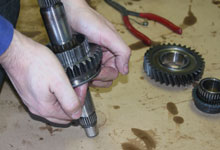
Bruce recommends mounting the the output, or "main",
shaft in a vice for disassembly. Clamp in the section
shown and not on the splines. A pair of pry bars placed
behind the 3rd speed gear help slide the gear and synchronizer
assembly off the shaft. |
|
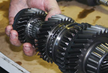
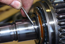
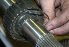
 Note the needle bearings under the gears (3rd speed
gear shown being removed). This is a major difference
between World Class and standard T5 transmissions. On
a standard T5 the gears ride directly on the shaft.
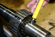
Note the needle bearings under the gears (3rd speed
gear shown being removed). This is a major difference
between World Class and standard T5 transmissions. On
a standard T5 the gears ride directly on the shaft.
|
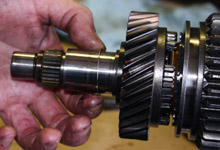
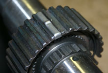
 Remove this spacer and save, as this part is not included
in the rebuild kits.
Remove this spacer and save, as this part is not included
in the rebuild kits. |
 Remove the snap ring and thrust washer.
 |
 Then remove the the 2nd speed gear, bearing and spacer.
|
 A thin retaining ring secures the 1-2 synchronizer assembly.
Use a small flat-blade screwdriver and gently guide the
ring out in a spiral fashion.
A thin retaining ring secures the 1-2 synchronizer assembly.
Use a small flat-blade screwdriver and gently guide the
ring out in a spiral fashion. |
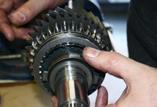
 The 1-2 thrust washer, inner and outer cone and blocking
ring can be slid off the shaft.
The 1-2 thrust washer, inner and outer cone and blocking
ring can be slid off the shaft.
|
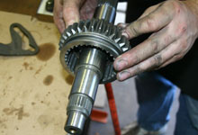
 Working on the other end of the shaft Bruce prys off the
5th driven gear and bearing cone, followed by the 1st
speed gear.
Working on the other end of the shaft Bruce prys off the
5th driven gear and bearing cone, followed by the 1st
speed gear. |
 With the shaft removed from the vice, the reverse gear
can be pushed off as shown.
With the shaft removed from the vice, the reverse gear
can be pushed off as shown. |
 Use a magnet to remove the pin or ball from the shaft.
This piece is tough to replace so do not discard or lose.
Use a magnet to remove the pin or ball from the shaft.
This piece is tough to replace so do not discard or lose.
|
 If we were reusing the stock output shaft it is recommended
to check it for runout. Modern Driveline uses a fixture
and dial indicator. Acceptable runout is below .005 inch.
Any more and the shaft should be replaced.
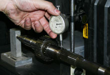
If we were reusing the stock output shaft it is recommended
to check it for runout. Modern Driveline uses a fixture
and dial indicator. Acceptable runout is below .005 inch.
Any more and the shaft should be replaced. |
 For our T5 buildup Modern Driveline will use a G-Force
"9310" high-nickel steel output shaft. This
piece, along with the G-Force gear set, is key to achieving
maximum strength.
For our T5 buildup Modern Driveline will use a G-Force
"9310" high-nickel steel output shaft. This
piece, along with the G-Force gear set, is key to achieving
maximum strength. |
 Transfer the two hook springs from the synchronizer hub
onto the new output shaft. There is one ring on each side
of the hub.
Transfer the two hook springs from the synchronizer hub
onto the new output shaft. There is one ring on each side
of the hub. |
 The hooked end of the springs lock into the hub inserts
as shown. The spring on the other side of the hub must
route in the opposite direction, and lock into the same
insert.
The hooked end of the springs lock into the hub inserts
as shown. The spring on the other side of the hub must
route in the opposite direction, and lock into the same
insert.
|
 Guide the reverse siding gear onto the synchronizer hub.
The inserts must be held in position as the gear is drawn
over the hub.
Guide the reverse siding gear onto the synchronizer hub.
The inserts must be held in position as the gear is drawn
over the hub. |