| |
Fabrication(continued)
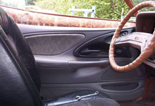
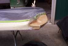
 As shown here, an area of the upper front door panel needed
to be removed to allow the panel to fit next to the dash.
A rough area was marked off and an initial cut to the
panel was made. We were cautious not trim too much material
by making several small cuts. After each cut we gently
tried closing the door. This was an ongoing process until
the door almost completely closed. Finally, the dash was
masked off to prevent any scuffing. With the door held
closed and using the dash as a guide, a more precise cut
line was established on the door panel.
As shown here, an area of the upper front door panel needed
to be removed to allow the panel to fit next to the dash.
A rough area was marked off and an initial cut to the
panel was made. We were cautious not trim too much material
by making several small cuts. After each cut we gently
tried closing the door. This was an ongoing process until
the door almost completely closed. Finally, the dash was
masked off to prevent any scuffing. With the door held
closed and using the dash as a guide, a more precise cut
line was established on the door panel. |
|
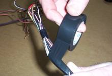
 Now that the Thunderbird door
panel was roughly fitted to the Ranchero door, we were
ready to integrate the Thunderbird inside door release
handles. A template was made by taping a sheet of paper
to the Thunderbird door (at the junkyard), covering
the cutout that the door handle slid into. The opening
outline was transferred to the paper and a small hole
was punched through at the point where a mounting screw
hole for the door pull had been marked. Using this hole
as a reference, the template was taped to the project
door, shown above. A simple pass over the paper with
paint from an aerosol can marked the location.
Now that the Thunderbird door
panel was roughly fitted to the Ranchero door, we were
ready to integrate the Thunderbird inside door release
handles. A template was made by taping a sheet of paper
to the Thunderbird door (at the junkyard), covering
the cutout that the door handle slid into. The opening
outline was transferred to the paper and a small hole
was punched through at the point where a mounting screw
hole for the door pull had been marked. Using this hole
as a reference, the template was taped to the project
door, shown above. A simple pass over the paper with
paint from an aerosol can marked the location.
|
| |
|
|
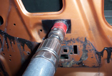
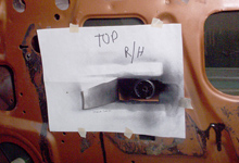
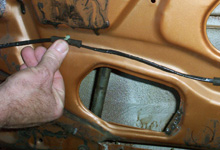
 With the location of the new inside
door release handle clearly marked on the project door,
all that was required was to remove the sheetmetal. A
hole saw was used to establish a hole and tin snips were
used to finish cutting the opening along the edge of the
blackened area. A flat file was then used to dress the
edges.
With the location of the new inside
door release handle clearly marked on the project door,
all that was required was to remove the sheetmetal. A
hole saw was used to establish a hole and tin snips were
used to finish cutting the opening along the edge of the
blackened area. A flat file was then used to dress the
edges.
|
|
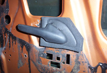
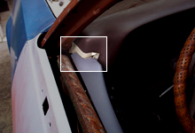
 With the inside releases now installed
on the doors, the panels are reinstalled to check for
proper location. The Thunderbird handles slide into the
opening and once slight adjustments were made front to
rear, two screws were used to lock them in place. Neither
the old nor the newer pull rods used to connect the inside
handle to the latch fit perfectly. The original rods gave
the best overall alignment.
With the inside releases now installed
on the doors, the panels are reinstalled to check for
proper location. The Thunderbird handles slide into the
opening and once slight adjustments were made front to
rear, two screws were used to lock them in place. Neither
the old nor the newer pull rods used to connect the inside
handle to the latch fit perfectly. The original rods gave
the best overall alignment. |
| |
|
|
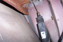
 An increase in length of approximately
1/2" was needed on the door-release pull rod. Using
a straight edge, a line was marked along the rod at one
end and two cross marks were made at a predetermined distance
apart. The rod was then cut in two. A small piece of tubing
was then slid over the rod pieces. Using the alignment
mark and adding 1/2" to the distance between the
cross marks the unit was tack welded together. A quick
test fit and the doors could be opened from the inside.
When removed, the rods were braised all around a both
ends. Next, we began the
installation of the power door locks.
An increase in length of approximately
1/2" was needed on the door-release pull rod. Using
a straight edge, a line was marked along the rod at one
end and two cross marks were made at a predetermined distance
apart. The rod was then cut in two. A small piece of tubing
was then slid over the rod pieces. Using the alignment
mark and adding 1/2" to the distance between the
cross marks the unit was tack welded together. A quick
test fit and the doors could be opened from the inside.
When removed, the rods were braised all around a both
ends. Next, we began the
installation of the power door locks. |
|
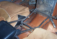
 We've noticed that for many years
the door latch mechanisms used in Ford products are set
up to accommodate power door locks whether they are installed
or not. The latches on our project car were no different
and only a hole at the back of the door, for mounting
purposes, was needed to install the power units from the
1995 Thunderbird. The location for these holes was very
difficult to mark on the inside of the door. A bit of
luck and guesswork was used in determining the hole location.
Once marked and center punched, a small hole was dilled
from the inside out. The hole was then enlarged by drilling
from the outside in. The push-pull rod was attached to
the door latch and the power lock attached to the door.
A power source and a pair of jumper wires were used to
check for proper operation.
We've noticed that for many years
the door latch mechanisms used in Ford products are set
up to accommodate power door locks whether they are installed
or not. The latches on our project car were no different
and only a hole at the back of the door, for mounting
purposes, was needed to install the power units from the
1995 Thunderbird. The location for these holes was very
difficult to mark on the inside of the door. A bit of
luck and guesswork was used in determining the hole location.
Once marked and center punched, a small hole was dilled
from the inside out. The hole was then enlarged by drilling
from the outside in. The push-pull rod was attached to
the door latch and the power lock attached to the door.
A power source and a pair of jumper wires were used to
check for proper operation. |
Wiring Harnesses and Schematics
Now that the door releases
and power lock mechanisms were installed, it was time to move
to the second stage of the upgrade. This phase will focus
on the adaptation of the door wiring harness from the Thunderbird
to the project vehicle. Many hobbyists dread working with
the electrical systems of their car. Working with a wiring
harness is, in our opinion, one of the easiest components
in the electrical system to create or repair.
The key to working with a wiring harness
is to have a clear objective. Understanding color codes and
what components the color codes correspond to is mandatory
and simple if you have a wiring schematic. We suggest making
enlarged copies of the appropriate schematic and identifying
what wires and components you will be working on. If you have
a basic plan you will succeed. After all, it's as simple as
connecting point A to point B.
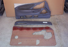
Wiring for Door Locks and Power Windows
To begin the wiring phase of our door panel upgrade, we needed
to identify all the required wires in the Thunderbird harness.
Unnecessary wires were to be elimated. The first step was
to mark wires needed for the door locks, power windows, power
mirrors, etc. with masking tape and a marker. The panel light
at the rear of the door uses a separate, two-wire harness,
and it was set aside. There would be no need for the wires
used by the Thunderbird keyless entry and door ajar warning
system. After removing most of the tape on the wiring harness,
the wires needed for the keyless entry and door ajar system
were eliminated. The wires and connector for the power mirrors
were identified and set aside for future use.
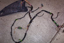
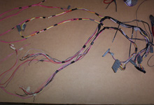
 The factory door panel harness
was removed from the Thunderbird. We removed the tape
for access to the wire bundles. Care was taken not to
cut or remove any insulation from any of the wires.
The factory door panel harness
was removed from the Thunderbird. We removed the tape
for access to the wire bundles. Care was taken not to
cut or remove any insulation from any of the wires. |
|
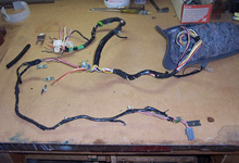
 By referring to a 1995 Thunderbird
schematic, we marked all the wires needed for the door
locks, power windows, power mirrors, etc. with masking
tape and a marker. The panel light at the rear of the
door uses a separate two-wire harness, which we did not
need.
By referring to a 1995 Thunderbird
schematic, we marked all the wires needed for the door
locks, power windows, power mirrors, etc. with masking
tape and a marker. The panel light at the rear of the
door uses a separate two-wire harness, which we did not
need. |
| |
|
|
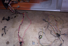
 Next, we removed all the wires
for the keyless entry, door ajar warning system, and power
mirrors. That left us with a nice pile of wires that we
did not have to deal with. Now we started the process
of installing the harness into the project door.
Next, we removed all the wires
for the keyless entry, door ajar warning system, and power
mirrors. That left us with a nice pile of wires that we
did not have to deal with. Now we started the process
of installing the harness into the project door. |
|
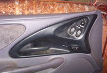
 We started the temporary installation
of the harness by connecting it to the switches in the
door panel and then installing the door panel onto the
vehicle. This provided a starting point for the harness
placement.
We started the temporary installation
of the harness by connecting it to the switches in the
door panel and then installing the door panel onto the
vehicle. This provided a starting point for the harness
placement. |
| |
|
|
|
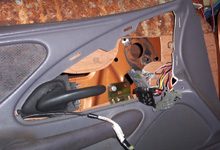
 All corrections or additions
were done as we worked away from the factory connectors
at the switch panel. The wires were massaged to lie
in their new positions with the main bundle going forward
and the other going toward the rear of the door. The
main forward bundle would eventually find its way through
the stock bellow.
All corrections or additions
were done as we worked away from the factory connectors
at the switch panel. The wires were massaged to lie
in their new positions with the main bundle going forward
and the other going toward the rear of the door. The
main forward bundle would eventually find its way through
the stock bellow.
|
|
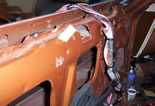
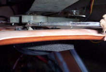
 A metal bracket was used to attach
the main harness at the front of the door, keeping the
harness away from the moving glass on the inside of the
door. A second insulated, loop-type clamp was used to
locate the harness to the outer side of the doo, this
was simply attached to a protruding hinge-bolt.
A metal bracket was used to attach
the main harness at the front of the door, keeping the
harness away from the moving glass on the inside of the
door. A second insulated, loop-type clamp was used to
locate the harness to the outer side of the doo, this
was simply attached to a protruding hinge-bolt. |
| |
|
|
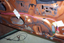
 It was obvious that the wires for
the power window motors and the power door locks were
well short of the required length. An additional hole
was needed to allow the power window connector to be on
the outside of the door yet behind the panel. Masking
tape and wire ties were used to locate the wires in approximate
locations.
It was obvious that the wires for
the power window motors and the power door locks were
well short of the required length. An additional hole
was needed to allow the power window connector to be on
the outside of the door yet behind the panel. Masking
tape and wire ties were used to locate the wires in approximate
locations. |
|
 Using wire of the same gauge and
color, we fitted the wire in-line between the factory
connectors to add additional length. The work done to
this point was all performed on the driver's door and
harness. You can easily see the additional length added
to the yellow, white, and pink wires.
Using wire of the same gauge and
color, we fitted the wire in-line between the factory
connectors to add additional length. The work done to
this point was all performed on the driver's door and
harness. You can easily see the additional length added
to the yellow, white, and pink wires. |
| |
|
|
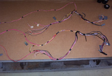
 On the bench and using the left
driver's side harness as a pattern, we duplicated the
harness for the passenger side.
On the bench and using the left
driver's side harness as a pattern, we duplicated the
harness for the passenger side. |
|

 Once both harnesses were roughed
out, the wire bundles were laid out neatly. Wrapping the
wires tightly with electrical tape at random points made
wrapping the entire harness much easier. We added wires
for the door mounted speakers.
Once both harnesses were roughed
out, the wire bundles were laid out neatly. Wrapping the
wires tightly with electrical tape at random points made
wrapping the entire harness much easier. We added wires
for the door mounted speakers. |
| |
|
|
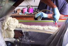
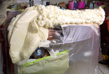
 We wrapped the entire harness.
The "dry vinyl wrap" shown is from Eastwood.
Since the final length of the harness going through the
cowl was not yet determined, an additional length was
wrapped as a precautionary measure. It's easier to remove
the harness tape and shorten the harness than to be forced
into extending it.
We wrapped the entire harness.
The "dry vinyl wrap" shown is from Eastwood.
Since the final length of the harness going through the
cowl was not yet determined, an additional length was
wrapped as a precautionary measure. It's easier to remove
the harness tape and shorten the harness than to be forced
into extending it. |
|
 Now that the wire harness was finished
it was reinstalled one final time. Proper fit was checked
and the snap-in-clips for locating sub-sections of the
harness to the door were installed. These are the same
clips that were removed from the original harness used
in the Thunderbird. The clips were installed at various
points using existing holes and fastened to the harness
using friction tape just as they were by the manufacturer.
Now that the wire harness was finished
it was reinstalled one final time. Proper fit was checked
and the snap-in-clips for locating sub-sections of the
harness to the door were installed. These are the same
clips that were removed from the original harness used
in the Thunderbird. The clips were installed at various
points using existing holes and fastened to the harness
using friction tape just as they were by the manufacturer.
|
What's Coming Next?
In part two of this upgrade the Thunderbird door panels
will be permanently attached to the mounting panels and then
molded together as a unit. The doors will be prepped as needed
and readied for paint. In an effort to provide mounting integrity,
several pieces of sheet metal will be welded on to the door
to provide a place for fasteners. Here is a preview.

|