|
by Chirag Asaravala. Drawings adapted
from Crane Cams.
By the time you get done reading this tech article you may
be disappointed with your conventional roller rocker arms.
Don't be too discouraged though, a good set of stud mount
roller rockers are fine for most applications. However, if
you've got a competition oriented motor with super high spring
rates, a .600" lift or greater solid roller cam, and
power that goes from 5000 on up, then the information presented
here is precisely for you. Most power mongers are well aware
of the hierarchy of rocker arm technology. Roller-tip arms
are better than stock sled style. Full rollers are even better
and the most common choice amongst enthusiasts. Shaft mount
rockers are the cream of the crop and often selected by the
most serious of racers. However, not all shaft rockers are
the same and whether you are in the market for shaft rockers
or not, you'll find the latest technology to be eye opening.
The challenge with pushrod engines is overcoming the limitations
in valve speed due to the inefficiencies of the mechanical
linkage that is the lifter, pushrod, and rocker arm. Overhead
camshaft (OHC) engines have set the benchmark. By locating
the camshaft over the valves, the valves respond directly
to the cam lobe profile. As a result, valve speed is much
quicker and lobe profiles can be very aggressive as there
are none of the geometrical limitations resulting from lifter
or rocker angles. The lifter design in a pushrod engine offers
up some challenges. Flat tappet lifters are quick off the
base-circle of the camshaft, but the valve lift rate is limited
by the profile of the cam lobe, which must be gradual in order
to prevent the tappet from digging in. Roller rockers, due
to their weight, are slow off the base circle but their infinite
contact area against the cam lobe offers the ability to design
very aggressive lift rates.
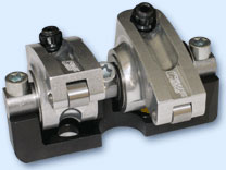
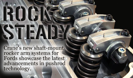
Crane Cams has spent considerable effort in developing technologies
which bring pushrod valve trains even closer in performance
to the OHC precedent. Their latest shaft rocker systems for
small block Fords incorporate two major advances in rocker
arm ratio and bearing design which result in significant power
and durability over conventional roller rockers. Let's take
a detailed look at how these two enhancements work.
Rocker Arms: Translation versus Multiplication
The most basic function of a rocker arm is to translate the
motion of the camshaft to the valve. Early engineers were
content to leave it at that, disregarding the notion that
a rocker arm could also serve to enhance valve activity. Crane's
founder, Harvey Crane, was also of the opinion that the rocker
arm should only be translation device, and all valve timing
activity is ground into the cam. This thinking didn't change
in the automotive industry until well after WWII, when automotive
engineering began to pick up again. Many of the advancements
in rocker arm technology, including the two presented here,
are the brainchildren of Ralph Johnson, legendary engineer
for Smokey Yunick, GM, Holley and Ford. In fact, even Ford
guys should appreciate that Ralph Johnson was on the original
small block Chevy design team at GM, and it was his father's
company that supplied the original stamped steel rocker arms
for those engines.
The idea of using a rocker arm as a multiplication device
is quite simple. By acting as a lever the mechanical advantage
serves to multiply the lift at the cam lobe to increase the
overall valve lift or distance the valve opens off the seat.
The amount of multiplication is termed the rocker arm ratio.
A rocker arm ratio of 1.6:1, for instance, would indicate
the arm moves the valve 1.6 times that of the lobe lift at
any given point. If the cam specifications indicate a max
lobe lift of .350", a 1.6:1 rocker arm would result in
the valve moving .560" off the valve seat.
If you look at any cam card you will see listed the maximum
valve or lobe lift. We deliberately used that same figure
in our example above to set up  another
important point - rocker arms are not really a fixed ratio.
The rocker arm ratio is theoretically calculated by dividing
the perpendicular distances from roller-tip centerline to
fulcrum and pushrod-cup centerline to fulcrum (see right.)
However because these points move in an arc, as the pushrod
rises and valve drops, the rocker arm ratio also varies. Early
factory rocker arm designs would start off the valve at significantly
less ratio than maximum. For instance, a 1.6:1 OEM rocker
arm would start off as low at 1.47 and approach 1.6 at max
lobe lift. It is likely this gradual multiplication was largely
designed to keep the early two piece valves from breaking
by slamming closed too quickly. another
important point - rocker arms are not really a fixed ratio.
The rocker arm ratio is theoretically calculated by dividing
the perpendicular distances from roller-tip centerline to
fulcrum and pushrod-cup centerline to fulcrum (see right.)
However because these points move in an arc, as the pushrod
rises and valve drops, the rocker arm ratio also varies. Early
factory rocker arm designs would start off the valve at significantly
less ratio than maximum. For instance, a 1.6:1 OEM rocker
arm would start off as low at 1.47 and approach 1.6 at max
lobe lift. It is likely this gradual multiplication was largely
designed to keep the early two piece valves from breaking
by slamming closed too quickly.
QuickLift™
The geometry of the rocker arm determines the rate at
which a rocker arm ratio is achieved. By changing the location
of the pushrod seat relative to the center of rotation of
the rocker arm, the rocker ratio can be achieve in one of
three way. It can gradually approach the maximum ratio, stay
fairly constant, or, as in the case of Crane's QuickLift design,
the ratio can start off high and then tapers down to the final
ratio.
Tailoring valve performance into the rocker arm offers
advantages over utilizing only camshaft lobe profiles. For
one, as mentioned earlier, there are limitations presented
by the lifter type. While roller lifters offer the ability
to use aggressive lobes, there is still a limit to how fast
the lifter  can
move. "In the end, the engine only responds to the valve,
it doesn't care whether the added lift, duration or valve
acceleration is due to the cam or the rocker arm." says
Mark Campbell, Vice President of R&D at Crane Cams. By
moving the pushrod seat down further in relation to the center
of rotation, the pushrod cup travels upward and outward along
its arc. (See right.) The result is very quick valve opening,
and at a much higher initial ratio. For example, a 1.60:1
Crane shaft rocker arm with QuickLift technology will come
off the seat at 1.72:1 up until .200" valve lift. Then
it will taper down to 1.62:1 and maintain this until the valve
returns to 0.200" and the ratio is back to 1.72:1 on
the seat. This does result in closing the valve harder against
the seat, however with aftermarket one piece valves and high
quality valvetrain hardware, this is not an issue. The benefit
of a quick opening is two fold. First, there is as much as
six degrees more duration in the low lift range. Secondly,
this is achieved with the same seat-to-seat timing. The intake
valve, for instance, is opening more and thus enabling greater
cylinder fill, and then closing fast. This is not only measurable
with a degree wheel and dial indicator but also on the dyno,
where roller rockers with QuickLift put out 15-18 more horsepower
than rocker arms which works up towards the advertised ratio
at maximum lift. can
move. "In the end, the engine only responds to the valve,
it doesn't care whether the added lift, duration or valve
acceleration is due to the cam or the rocker arm." says
Mark Campbell, Vice President of R&D at Crane Cams. By
moving the pushrod seat down further in relation to the center
of rotation, the pushrod cup travels upward and outward along
its arc. (See right.) The result is very quick valve opening,
and at a much higher initial ratio. For example, a 1.60:1
Crane shaft rocker arm with QuickLift technology will come
off the seat at 1.72:1 up until .200" valve lift. Then
it will taper down to 1.62:1 and maintain this until the valve
returns to 0.200" and the ratio is back to 1.72:1 on
the seat. This does result in closing the valve harder against
the seat, however with aftermarket one piece valves and high
quality valvetrain hardware, this is not an issue. The benefit
of a quick opening is two fold. First, there is as much as
six degrees more duration in the low lift range. Secondly,
this is achieved with the same seat-to-seat timing. The intake
valve, for instance, is opening more and thus enabling greater
cylinder fill, and then closing fast. This is not only measurable
with a degree wheel and dial indicator but also on the dyno,
where roller rockers with QuickLift put out 15-18 more horsepower
than rocker arms which works up towards the advertised ratio
at maximum lift.
Bearing Design
Conventional roller rocker arms have two predominant bearing
designs, caged bearings and "full complement" roller
bearings. Both designs are subject to two factors; internal
friction and bearing inertia. In a caged bearing design the
friction is between the roller and the cage. In a full complement
bearing, where there is no cage, the needles move in the same
direction but the contacting surfaces turn opposite of each
other,  creating
friction. Friction increases with bearing speed and is also
proportional to spring load. The stiffer the valve springs
and the higher you spin the motor, the greater the resulting
friction and heat, in the oil. In fact, compared to the Polymer
Composite Matrix bearing design, Crane Cams has measured a
full 100°F temperature increase in the oil around needle-bearing
rocker arms. creating
friction. Friction increases with bearing speed and is also
proportional to spring load. The stiffer the valve springs
and the higher you spin the motor, the greater the resulting
friction and heat, in the oil. In fact, compared to the Polymer
Composite Matrix bearing design, Crane Cams has measured a
full 100°F temperature increase in the oil around needle-bearing
rocker arms.
Bearing inertia is the other factor that robs power and generates
tremendous friction at high engine speeds. Because a rocker
arm does not rotate a full 360 degrees, but rather oscillates
in a limited motion, the bearings must turn one direction
as the valve is opening, then stop and reverse direction as
the valve is closing. This not only contributes to the friction
and parasitic power loss, but results in compromised durability.
Bearings are best suited when the entire surface area wears
evenly. Due to the limited rotation of a roller rocker the
bearings wear unevenly. This results in an oval shape which
can lead to rocker arm failure. A full set of 16 V-8 rocker
arms has 552 needle bearings, so it is easy to appreciate
the magnitude of the problem.
Polymer-Matrix Composite Bearings
Crane's polymer-matrix composite (PMC) bearing
prototype was actually first run back in 1992 at Daytona in
Sterling Marlins car. While even today Nascar teams change
out Jesel shaft rockers every race or two, the PMC bearings
showed unprecedented durability, running 15,000 race miles
with minimal wear. The PMC bearing resembles a simple bushing.
However its construction is quite sophisticated. The steel
ring consists of a bronze overlay. The bronze surface serves
to anchor the proprietary polymer-matrix compound. Since the
bearing itself is relatively thin compared to a roller needle
or caged bearing, the shaft which it rides on can be proportionally
larger. In this case it is 5/8", which is as much as
3/16" larger than traditional shaft diameters. The larger
shaft results in greater rigidity and virtually eliminates
deflection of the rocker arm.
 |
| Bearing Designs From left to
right, PMC bearing, full-complement roller bearings, and
caged roller bearings. The thin walled PMC bearing enables
a larger shaft and eliminates point loading since the
load is spread across the full circumference of the shaft.
The full complement needle bearings generate high internal
friction and significant point loading on the shaft. Roller
rockers with caged bearings create the most load due to
the least surface area contacting the shaft. |
The clear advantage to the PMC bearing is in its elimination
of internal friction and bearing inertia (see above). There
is no component within the bearing which must stop and reverse
direction. Furthermore, the load on the shaft is spread evenly
around the circumference of the bearing, whereas in a roller
bearing design, loading occurs at points around the shaft.
Point loading increases shaft wear and friction.
|