|
Installation - Crane Sportsman Shaft-Mounted Rocker Arms
As you've probably now understand, the Sportsman or Pro-Series
shaft rockers are not meant to be a set of bolt-on rocker
arms. Though they can be used on a mild performance street/strip
car, and surely they will last forever, the maximum gains
come with very big camshafts (.650" is puny!) and stiff
spring pressures (250 seat and 600 open or greater). As a
result installation does require careful setup and consideration
regarding valve train components and geometry. Installing
the shaft rockers is not difficult, but it is also not a simple
bolt-on affair as out-of-the-box small-block Ford heads will
require some modification. Certainly the valves will need
to be changed in most heads, as Crane designed the rockers
assuming most guys will run a 0.100" taller valve due
to the high spring pressures required with big solid roller
cams.
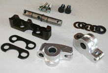
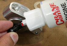
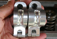
 Shown is one cylinders worth of
hardware from Crane's Sportsman shaft-mounted rocker arms.
We're using part number 44808-1 which is a 1.6:1 advertised
ratio, for aftermarket SBF heads with standard valve centerlines.
Shown is one cylinders worth of
hardware from Crane's Sportsman shaft-mounted rocker arms.
We're using part number 44808-1 which is a 1.6:1 advertised
ratio, for aftermarket SBF heads with standard valve centerlines. |
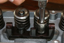
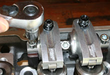
 The first steps are to check for
proper rocker arm and head geometry. Bolt a shaft mount
stand to any intake/exhaust pair on the head using the
supplied 12-pt fasteners (torque to 65lb.ft.) Note the
cutout in the stand is positioned facing the valves.
The first steps are to check for
proper rocker arm and head geometry. Bolt a shaft mount
stand to any intake/exhaust pair on the head using the
supplied 12-pt fasteners (torque to 65lb.ft.) Note the
cutout in the stand is positioned facing the valves. |
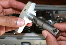
 Place the supplied dummy rocker
arm (geometry check tool) on a shaft and install onto
the stand. Secure the shaft with the supplied T-45 Torx™
bolts. Unless your cylinder head has different length
intake and exhaust valves, or the stud bosses have been
milled previously, you only need to check one valve at
any one cylinder.
Place the supplied dummy rocker
arm (geometry check tool) on a shaft and install onto
the stand. Secure the shaft with the supplied T-45 Torx™
bolts. Unless your cylinder head has different length
intake and exhaust valves, or the stud bosses have been
milled previously, you only need to check one valve at
any one cylinder. |
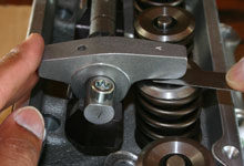
 With the check tool rocked back
so the dowel is resting on the stand, measure the clearance
between the check tool and valve stem. The ideal clearance
is 0.030". Less clearance will require use of the
supplied .050" or .100" shims beneath the stand.
Excessive clearance requires using a taller valve, lash
cap, or milling the stud pads. We found a 0.100"
taller valve is required on most popular aftermarket SBF
heads.
With the check tool rocked back
so the dowel is resting on the stand, measure the clearance
between the check tool and valve stem. The ideal clearance
is 0.030". Less clearance will require use of the
supplied .050" or .100" shims beneath the stand.
Excessive clearance requires using a taller valve, lash
cap, or milling the stud pads. We found a 0.100"
taller valve is required on most popular aftermarket SBF
heads. |
 Once the geometry on the head is
verified the rockers can be prepared and installed. Start
by installing the pushrod adjusting screws into each rocker
arm. Use the supplied assembly lube on the threads.
Once the geometry on the head is
verified the rockers can be prepared and installed. Start
by installing the pushrod adjusting screws into each rocker
arm. Use the supplied assembly lube on the threads. |
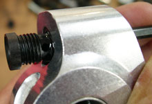
 The pushrod screw need to be threaded
completely up in to the body then backed out one turn
to ensure the oil hole lines up with the galley in the
body. In no circumstance should the screw be adjusted
out of the body more than two revolutions. Oil restrictors
should not be used in the lifter galleys.
The pushrod screw need to be threaded
completely up in to the body then backed out one turn
to ensure the oil hole lines up with the galley in the
body. In no circumstance should the screw be adjusted
out of the body more than two revolutions. Oil restrictors
should not be used in the lifter galleys. |
 Secure the pushrod seat with the
supplied 12-point jam nut and washer. Torque to 24lb.ft.
Secure the pushrod seat with the
supplied 12-point jam nut and washer. Torque to 24lb.ft. |
 Install one snap-ring onto the
center groove in each of the eight rocker arm shafts.
Use a pair of quality snap-ring pliers and avoid scarring
the shaft surface.
Install one snap-ring onto the
center groove in each of the eight rocker arm shafts.
Use a pair of quality snap-ring pliers and avoid scarring
the shaft surface. |
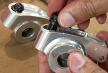
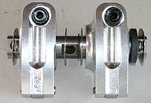
 The exhaust (left) and intake (right)
rocker arms are different as shown here and cannot be
interchanged as in a conventional stud mount rocker kit.
The exhaust (left) and intake (right)
rocker arms are different as shown here and cannot be
interchanged as in a conventional stud mount rocker kit. |
 This photo shows the proper rocker
spacer shim orientation. The dark 0.180" thick shim
should go to the right of each intake rocker arm.
This photo shows the proper rocker
spacer shim orientation. The dark 0.180" thick shim
should go to the right of each intake rocker arm. |
 The shafts are secured to the stands
with T-45 Torx fasteners. The shorter 1" fastener
goes in the middle shaft hole. Torque to 65lb.ft.
The shafts are secured to the stands
with T-45 Torx fasteners. The shorter 1" fastener
goes in the middle shaft hole. Torque to 65lb.ft. |
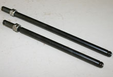
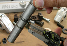
 The proper pushrod length is key
to making this set up achieve maximum power and durability.
The kit includes two push rod checking tools (302 and
351 deck heights.) Only use these with low-tension checking
springs or with the valves closed, they will break under
full spring pressure.
The proper pushrod length is key
to making this set up achieve maximum power and durability.
The kit includes two push rod checking tools (302 and
351 deck heights.) Only use these with low-tension checking
springs or with the valves closed, they will break under
full spring pressure. |
 The proper pushrod length
is achieved when the roller tip is slightly inboard of
the valve stem centerline when the valve is closed. The
roller tip should travel slightly outboard at mid-lift
and back towards center at full lift.
The proper pushrod length
is achieved when the roller tip is slightly inboard of
the valve stem centerline when the valve is closed. The
roller tip should travel slightly outboard at mid-lift
and back towards center at full lift. |

|


