|

Wiring
Wiring is what many people consider the hardest part of any
nitrous system installation. It is also what many people rush
and therefore mess up. If you take the time to wire the system
properly you will have a very safe and reliable system. The
system should always use a relay and a wide-open throttle
switch. On modular Ford engines, particularly those which
use a plastic composite intake manifold, a special precaution
must be taken to avoid fuel puddling and subsequent explosion.
With direct port fuel injection the plastic intake manifolds
were never designed to carry atomized fuel and air. As a result
their ultra smooth internal surfaces do a poor job of keeping
nitrous and fuel in suspension. At low rpms the air flow within
the intake is relatively slow and can cause fuel to puddle
in the intake. This can result in a backfire which easily
demolishes the plastic manifold.
To prevent this problem the nitrous and fuel solenoids should
only be activated when the engine is at wide open throttle
and above 3000 rpm-an engine speed where the airflow
into the intake is fast enough to keep the fuel atomized.
This activation of the solenoids at this rpm is controlled
by an electronic device known as a rpm window switch. The
switch actually provides ground for the micro throttle position
switch, which in turn activates the solenoids. The way the
entire system works is three fold. First, a master "Arming"
switch, usually mounted in the cockpit, must be turned on.
Secondly, the engine must be at the "on" rpm as
set in the window switch. Finally the throttle position must
be at wide-open throttle thus activating the micro throttle
switch. The rpm window switch simply provides a ground for
the micro throttle switch, so if the rpm of the engine is
not at the designated point the circuit is not complete and
the micro switch cannot activate the solenoids. The RPM window
switch also has an "off" rpm at which the circuit
is broken.
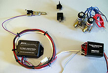
 The main components of the nitrous electrical system (clockwise
from top left); wide open throttle micro switch, arming
switch and relay, solenoids, tach adapter, and rpm window
switch unit.
The main components of the nitrous electrical system (clockwise
from top left); wide open throttle micro switch, arming
switch and relay, solenoids, tach adapter, and rpm window
switch unit. |
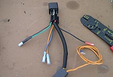
 Use a relay harness to easily make the connections.
See the side bar on relay wiring to understand where
to make the connections.
Use a relay harness to easily make the connections.
See the side bar on relay wiring to understand where
to make the connections.
|
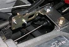
 We made a simple bracket and mounted
the micro-throttle switch to the upper intake plenum.
The switch is activated when the throttle is fully open
and the cable arm swings up and hits hits switch lever.
Wire the positive side of the switched, marked "NO
for normally open" to the relay. The ground terminal
connects to the purple wire of the BMN window switch.
We made a simple bracket and mounted
the micro-throttle switch to the upper intake plenum.
The switch is activated when the throttle is fully open
and the cable arm swings up and hits hits switch lever.
Wire the positive side of the switched, marked "NO
for normally open" to the relay. The ground terminal
connects to the purple wire of the BMN window switch. |
 The solenoid wiring has no polarity.
Properly ground to chassis one wire from each solenoid,
and connect the remaining two wires to terminal 87 on
the relay.
The solenoid wiring has no polarity.
Properly ground to chassis one wire from each solenoid,
and connect the remaining two wires to terminal 87 on
the relay. |
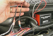
 Due to the coil on plug ignitions on these 4.6L engines
an Autometer Tach Adapter is required to feed the rpm
signal to the window switch. The Tach Adapter runs off
this coil trigger wire (pin#34) located in the computers
wiring harness on the passenger side fender in the engine
compartment. Do not look for a pin #34 or similar trigger
wire at the PCM.
Due to the coil on plug ignitions on these 4.6L engines
an Autometer Tach Adapter is required to feed the rpm
signal to the window switch. The Tach Adapter runs off
this coil trigger wire (pin#34) located in the computers
wiring harness on the passenger side fender in the engine
compartment. Do not look for a pin #34 or similar trigger
wire at the PCM. |
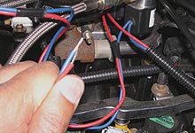
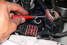
 Pull back the plastic wire loom to reveal a section of
the red wire which connects to pin #34. Cut the wire and
connect the solid red wire from the Tach Adapt to the
side still attached to the connector pin 34. Connect the
red/green striped wire to the other side of the harness
red wire. The black wire of the Tach Adapt goes to ground,
and white wire is the rpm feed to the window switch (it
can also run an aftermarket tachometer or shift light.)
Pull back the plastic wire loom to reveal a section of
the red wire which connects to pin #34. Cut the wire and
connect the solid red wire from the Tach Adapt to the
side still attached to the connector pin 34. Connect the
red/green striped wire to the other side of the harness
red wire. The black wire of the Tach Adapt goes to ground,
and white wire is the rpm feed to the window switch (it
can also run an aftermarket tachometer or shift light.) |
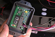
 The RPM window switch is the heart of our nitrous activation
system. This one is made by BMN
Racetech and runs $130. It works by providing the
ground to the microthrottle switch only when engine rpm's
are in the selected range. Under the cover are dip switches
and selector switches to set the number of cylinders and
rpm on and off points. Three LED's (power, brake, and
rpm) indicate when you have wired it up properly, as outlined
in the next step.
The RPM window switch is the heart of our nitrous activation
system. This one is made by BMN
Racetech and runs $130. It works by providing the
ground to the microthrottle switch only when engine rpm's
are in the selected range. Under the cover are dip switches
and selector switches to set the number of cylinders and
rpm on and off points. Three LED's (power, brake, and
rpm) indicate when you have wired it up properly, as outlined
in the next step. |
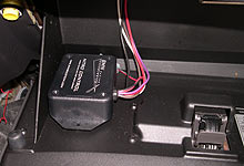
 We mounted the rpm switch in the glove box using velcro.
Wiring it up is simple. The red wire is ignition-on 12V.
Black is ground. White goes to the Tach Adapter feed from
step 6 (also a white wire.) The purple wire connects to
the ground terminal on the micro-throttle switch. Finally
the brown lead splices into brake light switch above the
brake pedal - this offers a quick way to kill the nitrous
by tapping the brakes. The switch also has a first gear
lockout option which can be activated to disarm nitrous
in first gear to minimize traction loss.
We mounted the rpm switch in the glove box using velcro.
Wiring it up is simple. The red wire is ignition-on 12V.
Black is ground. White goes to the Tach Adapter feed from
step 6 (also a white wire.) The purple wire connects to
the ground terminal on the micro-throttle switch. Finally
the brown lead splices into brake light switch above the
brake pedal - this offers a quick way to kill the nitrous
by tapping the brakes. The switch also has a first gear
lockout option which can be activated to disarm nitrous
in first gear to minimize traction loss. |
|
| |
|
 (Dyno
Results) (Dyno
Results)
|
|
|
|
|
| |
|
| |
|
| |
Relay Race
The proper way to control
a nitrous system is to use a standard five-terminal
30 amp relay as seen here. The use of a relay has
two major benefits. First it enables high current
demanding components, such as the solenoids, to
be controlled with a low current switch. Without
the relay the arming switch would have to be capable
of handling the high current flow to the solenoids.
This would also require larger gauge wiring and
increase the risk of fire or short.
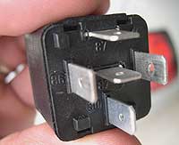
The second advantage to using a relay is that it
enables controlling multiple circuits. In the case
of a nitrous system we need to control a microthrottle
switch along with the solenoids. Four terminals
on the relay enable this to happen (terminal 87a
in the middle is not used).
Here is how to wire the system:
-
Terminal
30 will connect to the battery positive, using
a 30 amp fuse.
-
Terminal
85 will connect to our arming toggle switch under
the dash.
-
Terminal
86 connects to the positive side of the micro
throttle switch.
-
Terminal
87 will wire up to the nitrous and fuel solenoids.
Both solenoids can be spliced together as the
activate simultaneously.
|
|
|
|


