|

Copy and Photos by Jim Batie
Overview and
Background
On April 9, 1971, the National Highway Traffic Safety Administration issued its first regulation on passenger car bumpers. Federal Motor Vehicle Safety Standard 215, "Exterior Protection," was initially effective on September 1, 1972, and imposed requirements which prohibited damage to specified safety-related components such as headlamps and fuel systems in a series of perpendicular barrier impacts, at 5 mph for front and 2.5 mph for rear bumper systems. Subsequent pressure from manufacturers regarding the overkill of this mandate and the limitations it placed on design, forced an amendment to the Bumper Standard more than 10 years later.
The changes to the Bumper Standard effective
with the 1983 model year reduced required damage resistance
for passenger car bumpers from 5 mph front and rear
barrier impacts to 2.5 mph. The amendment proved the
initial mandate was not practical. Unfortunately, a
decade of "damage" had been done to body styles
that were otherwise contiguous and well-integrated.
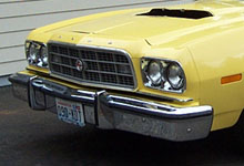
The '73 Ford Gran
Torino Sportsroof is a great example of an appealing body
design that was vastly affected by the 5 mph bumper. The combination
of the unusually large, extended, and heavy front bumper makes
for a very unbalanced look. Weighing well over 100 pounds,
the new bumper adds considerable weight to the front of the
car as well. Enthusiasts faced with any model incorporating
the 5 mph bumper must ask themselves, what can be done to
create a more balanced look and reduce weight in the front
end?
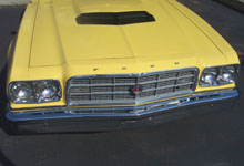
With careful attention
to detail and basic fabrication skills FordMuscle believed
the "battering ram" look could easily be restyled
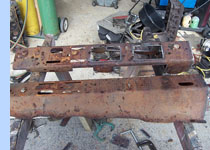
and its' weight reduced. We took on the project using a rare
1973 Gran Torino 4-speed sportsroof car. Since the current
bumper was in excellent condition, we chose to use a donor
vehicle's piece to perform our modification. We weighed the
bumper to establish a point of origin and found the assembly
totaled almost 120 lbs. Today, Ford enthusiasts who have collected
any vehicle with a 5 mph front bumper are left with a less
than optimum appeal and design.
Step 1 - Narrowing
the Face Bar
A simple square was used to scribe two parallel lines
centered exactly in the middle of the face bar. Extreme
care was used in cutting precisely on these lines to
ensure 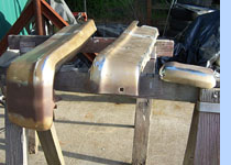 a
consistent and even edge. Next, the ends were to have
a similar section removed from them. This area presented
two problems as there is a bumper bolt on each end,
and it was too difficult to use the square to mark the
cuts. To solve this problem it was decided to remove
the material on the rear side of the bolt hole and simply
use masking tape to mark the lines. A three-inch section
was to be removed so a combination of two and one inch
tape applied side to side was used. The area was then
painted over, leaving a line to cut on, once the tape
was removed. This assured that both cuts would be parallel.
All cuts on the face bar were done with small hand held
grinder fitted with a 4-1/2" cut off wheel. a
consistent and even edge. Next, the ends were to have
a similar section removed from them. This area presented
two problems as there is a bumper bolt on each end,
and it was too difficult to use the square to mark the
cuts. To solve this problem it was decided to remove
the material on the rear side of the bolt hole and simply
use masking tape to mark the lines. A three-inch section
was to be removed so a combination of two and one inch
tape applied side to side was used. The area was then
painted over, leaving a line to cut on, once the tape
was removed. This assured that both cuts would be parallel.
All cuts on the face bar were done with small hand held
grinder fitted with a 4-1/2" cut off wheel.
Step 2 - Narrowing
the Support Beam
An identical two-inch section from the center of the support
beam was removed. By doing this all bumper bolt holes remained
in alignment. No cut was necessary on the ends as a bolt-on
support bracket was used to attach to the outside bumper bolt.
Remember that the end cuts were past the bolt hole and the
relative location remained the same.
Step 3 - Removing
Weight from the Support Beam
The support beam offered an excellent opportunity to
shave pounds. There is an extremely heavy and bulky
reinforcement assembly in the center of the support
beam where the center bumper bolts are located. 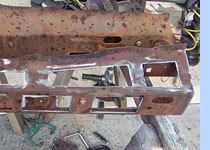 The
majority of this was removed leaving only the area surrounding
the bumper bolt holes. A piece of flat stock was then
welded in at each outside end providing structural support.
The center of the remaining reinforcement area would
later be welded when the two halves were joined back
together. After marking out the areas that would be
removed for additional weight savings, on one half,
several templates were constructed using 1/4 inch square
bar stock. The templates were then used to make matching
pattern cuts on both halves of the support beam. All
cuts were then cleaned and dressed with an air grinder.
Additionally, all areas were chamfered where butt welds
would be required. The
majority of this was removed leaving only the area surrounding
the bumper bolt holes. A piece of flat stock was then
welded in at each outside end providing structural support.
The center of the remaining reinforcement area would
later be welded when the two halves were joined back
together. After marking out the areas that would be
removed for additional weight savings, on one half,
several templates were constructed using 1/4 inch square
bar stock. The templates were then used to make matching
pattern cuts on both halves of the support beam. All
cuts were then cleaned and dressed with an air grinder.
Additionally, all areas were chamfered where butt welds
would be required.
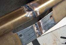
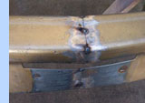
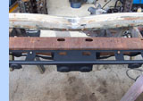
Step 4 - Finishing and Joining the Support Beam
In preparation for finishing the support beam the two halves
were sand
blasted. This was done before joining the two pieces,
as it gave better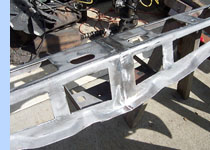 access to some of the internal structure and allowed
them to fit in a blast cabinet. With the aid of several
lengths of 1/4" X 3" flat stock, as straight
edges, the two halves were first clamped and then tack-welded
together. The support beam was then welded inside and
out. The outside welds were then ground flat while the
inside welds received attention only in highly visible
areas. After all, the goal in this project was to have
the bumper appear as a stock item.
access to some of the internal structure and allowed
them to fit in a blast cabinet. With the aid of several
lengths of 1/4" X 3" flat stock, as straight
edges, the two halves were first clamped and then tack-welded
together. The support beam was then welded inside and
out. The outside welds were then ground flat while the
inside welds received attention only in highly visible
areas. After all, the goal in this project was to have
the bumper appear as a stock item.
 |
 |
Step 5 - Tack
Welding and Test Fitting Face Bar with Support Beam
Reconstruction of the face bar and the task of joining the
four pieces into
one unit was the next step in the process. Luckily, the face
bar is a very
straight and uniform piece as viewed horizontally from the
front. The top edge is very flat and uniform. The center also
has a very flat surface where the license plate mounting bracket
fits. Both of these areas are a great help in assuring the
proper alignment of the two main pieces before, during and
after welding. An extremely flat section of floor was also
most useful. After clamping the sections together, checking
and rechecking for the correct alignment, several tack-welds
where made to the outside of the face bar on the top, front,
and bottom. With these three sides tacked, the unit could
now be test fitted to the support beam. With great care all
bolts were installed, checking for proper fitment and alignment
with the support. No bolts were tightened and with bit of
luck everything fit well and flush in their holes.
|