 |
 |
Step
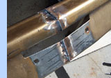
6 - Permanent Joining of Face Bar
After removing the face bar, several half-inch long
welds were made to the inside. Once this was done the
piece was quite sturdy and the process of permanent
welding began. The welds were done in stages and then
allowed to cool in between. After grinding the welds
any voids or pinholes were filled and smoothed. The
two end pieces did not require the precise alignment
of the main sections due to their compound curves. However
they did present their own unique problem. Because of
the compound curves the heights of the metal, on the
vertical surface, do not align. Luckily the top and
bottom of the sides retain an almost straight line just
like the rest of the bumper. Only very slight grinding
of the parts was required to assure proper positioning.
This is where the great care in cutting the pieces apart
really pays off. The top and bottom are tacked into
place inside and out. With a bit of heat, a hammer and
dolly, the two mismatched surfaces are worked into the
proper configuration. With several clamps in place the
smoothed area is welded. After the heavy grinding is
completed the final massaging is done, again with a
hammer and dolly, until the surface can be ground to
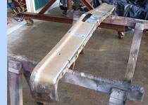
a smooth and uniform surface. It's much easier to work
with each half so this step was actually done prior
to the joining of the two halves as can be seen in the
pictures.
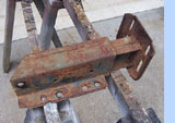
Step
7 - Modifying the Mounting Brackets
Not only are these brackets very heavy but they also
push the location of the bumper out in front of the
car. The energy absorption aspect of these brackets
is no longer of any importance and was eliminated. With
no particular plan in mind the units must first be dissected.
The only guide for this operation is the fact that the
finished brackets will have to be reconstructed from
pieces of the existing part while moving the bumper
back two inches. By removing the top and outside of
the box surrounding the
energy absorption unit, we were left with the portion
that bolts onto the frame, intact. This allowed further
inspection of the components within. As it turns out
there is a separate piece that attaches to the support
beam, sandwiched tightly into the outer assembly and
held in place by to large rubber blocks that are vulcanized
to the inner and outer metal sides. These rubber blocks
are easily removed by heating the metal with a torch
until the bonding agent releases.
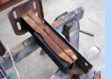
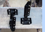
The two
components for the modified bracket can be prepped for
reassembly. These are identified as the frame section
(the part that bolts to the frame) and the front section
(the part that bolts to the support beam). Two inches
are next cut off, from the back, of the front section.
Following this, the inside edges of the H-beam design
were trimmed off. Approximately 1/8 to 1/4 of an inch
of material is left remaining, top and bottom. Even
though there is a great deal of adjustment built into
the assemblies, there was still a need to compensate
for the narrowing of the front beam. By removing this
material, from this area of the front section, it was
allowed to move toward the center of the car by almost
3/4 of an inch. Next, the front section is clamped to
the mounting section, making sure that the front section
is moved back two inches from its stock location. After
welding and a slight amount of boxing, the two bumper
brackets were ready to test fit the bumper.
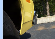
Step
8 - Test Fitting the Assembly
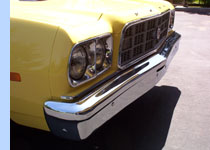
We used a second 73 as a test mule. This allowed for
a test fit without having to worry about damaging the
finish on the destination vehicle. When installing the
bumper it was quit obvious that it was going to be extremely
tight on the sides. With great care only minor surface
scratches were put in the paint on the fenders. With
the modified assembly now installed we assessed 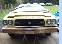 the
overall look and determined if the goals had been achieved.
With the exception of the fit on the ends it was an
astounding success. With the bumper still on the test
mule, we used masking tape to create a trim line that
would follow the body and set the new inner edge of
the bumper. Once off the car the majority of the excess
material was removed again using the cut of wheel. Using
a large air grinder, fitted with 7" 24 grit disc,
the end was ground until the contour of the edge matched
the edge of the masking tape. A smaller air grinder,
using first a 50 then an 80 grit disc, was used do achieve
a nicely smoothed edge with a nice radius. It was also
noticed that the very bottom of the mounting bracket,
front plate, was a little to visible under the face
bar when viewed from a distance. To correct this unsightly
condition, the very bottom of that plate was removed
to a point, even to the bottom, of what was the H-beam. the
overall look and determined if the goals had been achieved.
With the exception of the fit on the ends it was an
astounding success. With the bumper still on the test
mule, we used masking tape to create a trim line that
would follow the body and set the new inner edge of
the bumper. Once off the car the majority of the excess
material was removed again using the cut of wheel. Using
a large air grinder, fitted with 7" 24 grit disc,
the end was ground until the contour of the edge matched
the edge of the masking tape. A smaller air grinder,
using first a 50 then an 80 grit disc, was used do achieve
a nicely smoothed edge with a nice radius. It was also
noticed that the very bottom of the mounting bracket,
front plate, was a little to visible under the face
bar when viewed from a distance. To correct this unsightly
condition, the very bottom of that plate was removed
to a point, even to the bottom, of what was the H-beam.
Step
9 - Smoothing, Chroming, and Protecting the Face Bar
Since the look of the new bumper was to be very smooth
the bumper guards were not reinstalled. The holes for
the bumper guards were filled along with the two slots
for the jack. With a second successful test fit on the
mule the clearance problem was rectified. Pacific Plating
LTD., Of Vancouver B.C., performed the chroming of the
face bar. Once received, it was cleaned thoroughly and
the inside was given two coats of gray epoxy primer.
This gave a nice look to the inside and prevents any
rust from occurring in the future. The original bumper
bolts were used to attach the face bar to the support
beam. With no damage to them beyond normal wear and
tear, we had them replated with the rest of the hardware.
The stainless steel caps were then sanded, to eliminate
the cad plating and any irregularities, then polished
to a chrome like finish.
Step
10 - Modifying the Filler Panel
This particular bumper assembly uses a filler panel,
painted the color of the car, to bridge the gap between
the body and the bumper. This gap was created when the
unit was pushed forward as part of the impact standard.
Although this filler panel could probably be left out,
the decision was made to retain it. From the exterior
it will be all but invisible. Painted the exterior color
it will eliminate the look of a dark void between the
body and the bumper and the possibility of seeing the
ground through the gap. From under the hood it eliminates
the view of the bumper brackets, the inner structure
and helps to give a more finished look. The panel needed
to be moved toward the engine compartment the same two
inches that the bumper was moved back. 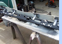 The
panel mounts to the support beam by the means of a single
bolt in each of four mounting stands. These stands were
now all one inch to the outside of the taped bolt holes.
The easiest solution would have been to just drill and
tap new holes. Although hindsight is 20/20, this simplest
of solutions was surly missed. Unfortunately, there
was no longer any metal left where these holes would
need to be located. Instead of cutting two inches out
of the center of the filler panel, it was decided that
moving the mounting stands would make more sense. The
first stand was removed from the panel by drilling out
the spot welds from underneath. The panel was then centered
on the support beam, using the three remaining stands,
in line with the bolt holes and clamped in place. The
stand that was removed, was then bolted to the beam,
and clamped onto the panel in its new location. After
removing the panel, the stand was welded to the panel,
through the holes left from drilling the spot-welds
out. The panel is now reinstalled after removing the
next stand, again using clamps on the two remaining
stands and a bolt in the one relocated stand. The process
is repeated on the next two stands. Only minimal bodywork
was needed on the panel where the spot welds have been
made. Once the panel was repainted and dry it was masked
off to allow a 3" section on the backside to be
painted the same semi-flat black color used elsewhere
under the hood. The
panel mounts to the support beam by the means of a single
bolt in each of four mounting stands. These stands were
now all one inch to the outside of the taped bolt holes.
The easiest solution would have been to just drill and
tap new holes. Although hindsight is 20/20, this simplest
of solutions was surly missed. Unfortunately, there
was no longer any metal left where these holes would
need to be located. Instead of cutting two inches out
of the center of the filler panel, it was decided that
moving the mounting stands would make more sense. The
first stand was removed from the panel by drilling out
the spot welds from underneath. The panel was then centered
on the support beam, using the three remaining stands,
in line with the bolt holes and clamped in place. The
stand that was removed, was then bolted to the beam,
and clamped onto the panel in its new location. After
removing the panel, the stand was welded to the panel,
through the holes left from drilling the spot-welds
out. The panel is now reinstalled after removing the
next stand, again using clamps on the two remaining
stands and a bolt in the one relocated stand. The process
is repeated on the next two stands. Only minimal bodywork
was needed on the panel where the spot welds have been
made. Once the panel was repainted and dry it was masked
off to allow a 3" section on the backside to be
painted the same semi-flat black color used elsewhere
under the hood.
Final
Installation and Conclusion
The last step prior to, or during, installation was
the required trimming of the plastic fender extensions
that fit under the die cast fender extension that houses
the headlamps. This is strictly a trim to fit operation.
Pay special attention to the very bottom, as it will
need less trimming due to the curve at the bottom of
the face bar.
There were
several lessons learned from this first attempt. We
already touched on the ease of remounting the filler
panel, if before
lightning the support beam, new holes were drilled for
the mounting bolts. Removing a narrower section from
the center of the face bar would have increased the
gap between the fender and bumper on each side. Similarly
taking less material out of the ends may help the overall
appearance. This step could also be eliminated if so
desired. Finally if the front section of the bumper
bracket was raised about 3/8" before welding it
to the mounting section, the need for the cosmetic trim
of the bottom of the brackets front mounting plate would
have been eliminated.
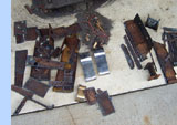
As evidenced
by the debris pile shown above, the total mass started
at 118 pounds. The finished product weighed in at 72
pounds. A total savings of 46 pounds was achieved. 
|