
1. If you are converting
over from the stock mechanical clutch, begin by removing
all the stock linkage. You wont need any of it except
the clutch pedal.
Shown is the typical linkage from a 67-68 Mustang. The
reduction in moving parts is astonishing: Upper and lower
pushrods, "z" bar, upper and lower return springs,
underdash bracket and spring, block and frame pivots,
and special bellhousing pivot mount required when using
late-model 302 blocks without a pivot mount provision.
|
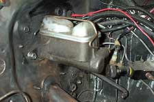
2. The master cylinder (and
booster if present) need to be removed from the firewall
in order to mount the cable support bracket. With manual
brakes you can typically pull the pushrod out of the cylinder
bore, and then slightly pull the master cylinder away
from the firewall and slide the support plate between
the master and the firewall.
With power brakes you will most likely need to remove
the entire assembly in order to get the bracket into place.
You should only have to disconnect the two main lines
at the master cylinder. Always use a flare nut wrench
when removing brakelines. |
3. Place the supplied support
bracket against the firewall and mark the firewall at
the cable passthrough. On a 65-66 Mustang the firewall
is a flat surface and the bracket will sit flush, whereas
on a 67-70 Mustang there will exist a gap behind the top
of the bracket. |

4. Remove the bracket and
drill a hole at the marked location. The kit instructions
call for a 9/16" hole using a uni-bit. We didn't
have such a bit, so we drilled a pilot hole and stepped
it up to the largest bit we had (1/2"). |
|
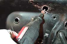
5. Because the firewall
angles back on a 67-70 Mustang, we had trouble drilling
straight on. We ended up making another 1/2" hole
above the first, then blending the two holes together
with a Dremel and grinding bit. The result is an oval
hole 1/2" wide and 1" tall. This will allow
plenty of room for unobstructed cable travel, and also
for the adjuster to pass through when fully screwed
in.
|
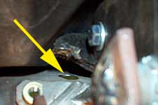
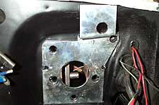
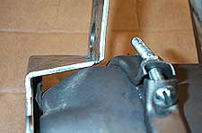
6. The arrow shows the hole
as it appears from under the dash. Note how the kit is
designed to place the cable pivot point at the highest
point possible under the dash/cowl. For this reason it
is not wise to modify or reposition the support bracket. |
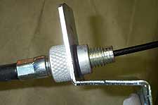
7. With the firewall hole
drilled and edges deburred we'll assemble the cable and
support plate. Remove the o-ring from the adjuster, pass
the cable and adjuster through the bracket, then replace
the o-ring to secure the adjuster in place. |
8. Next we will connect
the cable to the clevis/pedal bracket. You will need to
go under the dash and feed the bracket up so the clevis
protrudes through the firewall. Then thread the cable
into the clevis. (Use a vise-grips to secure the bracket
temporarily, or have a buddy hold it in place.) |
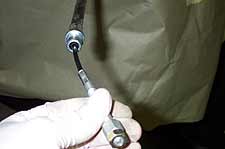
9. Thread the cable into
the clevis completely by holding the cable straight out
and turning the clutch end of the cable. |

10. Another way to connect
the cable to the clevis is to bolt the support bracket
to the firewall, then from under the dash pull the cable
down as far as possible. Now you can take the pedal bracket,
hold it in one hand by the clevis, and spin it on the
threaded end of the cable. Be sure to secure the jam nut. |
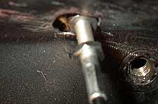
11. With
the cable secured to the clevis, the pedal bracket can
be mounted to the clutch pedal using the supplied bolt
and nylock nut. The bracket mounts using the existing
pushrod hole in the pedal. Note the open hole in the firewall
for the mechanical pushrod, we'll cover this with a plug
provided in the kit. |

12. Due to the difficulty
in taking pictures under the dash we've removed the pedal
out of the car to show you how the cable bracket attaches.
Note how the bracket is made to bolt to the existing pushrod
bracket, no modification is neccesary. However you must
have the correct clutch pedal for your model and year
Mustang. If you attempt to use a 67-68 pedal, for example,
in a 65-66 car the cable will not line up correctly. |

13. Reattach the master
cylinder (and booster if applicable) and associated brake
lines. Be sure to reconnect the master cylinder pushrod
to the brake pedal under the dash. If you disconnected
any brake lines be sure to reattach and bleed the entire
system. |
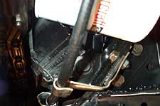
14. Route the clutch cable
around the oil filter and below the motor mount. The kit
includes a small bracket intended to mount off an oil
pan bolt, however this pulled the cable to close to the
header tube. We fabricated a bracket to secure the cable
away from the header tubes, and also to position it inline
with the entry point in the bellhousing. |
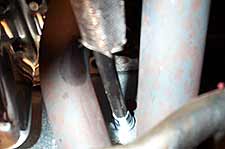
15. Some headers may pose
a clearance problem for the cable. We're using Hooker
Super Comps which have a large gap between the four tubes,
allowing the cable to clear with about 3/8" clearance.
Using the supplied heat resistant sleeve for additional
heat protection. |
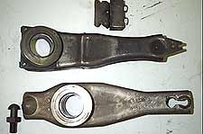
16. Before securing the
cable to the bellhousing we need to change our mechanical
"push" style clutch fork (top) to
a late-model "pull" style. This obviously
requires removal of the transmission.
|
17. The pull style fork
pivots on ball mounted on the right side of the bellhousing,
while the push type fork sits on a pivot ledge. The throwout
bearings are also different, specify on for a 87-95 Mustang
and you'll be fine. |

18. Though not absolutely necessary, it is recommended
that you use a late-model diaphragm style clutch. The
release rate of the belvile springs are designed for a
cable mechanism, whereas long-style "three finger"
clutches are designed around mechanical linkage. If you
do use the latter with the cable mechanism you should
ensure there is sufficient fork travel to release the
clutch properly, and also check for about 1/8" air
gap between the throwout bearing and clutch fingers when
the clutch is engaged. |

19. We ended up ordering a Stage 3 SPEC clutch.
The clutch uses a diaphragm style pressure plate, which
is shorter in height than a long style and thus clears
up our cable length problems. The SPEC clutch disc is
composed of six carbon metallic paddles, and is rated
to hold 600 horsepower, without the aggressiveness of
the sintered iron we were using previously.
|

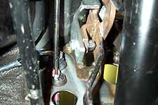
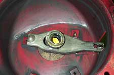
20. With the clutch and bellhousing mounted, the cable
end is passed through the bellhousing flange. Secure the
cable to fork nut and jam nut.
Using the firewall adjuster we can fine tune the cable
length to get the pedal height and release point we desire.
|
|

21. The Modern Driveline
kit is designed to work using the stock 8" power
booster found on 65-70 Mustang. We however had a 9"
booster from an MPBrakes power conversion kit for 67-70
Mustangs. As seen in this photo the support plate interferes
with the booster body.
It's tempting to bend and grinding the plate to make
it clear, however Modern Driveline does not advocate
this because it is likely to reposition the cable hole
and lead to alignment problems with the clevis assembly.
|
22. The only option for
us was to pick up a stock 8" booster (rebuilt). While
the plate fits much better, we still needed to grind slightly
on the corner of the support plate for the booster to
sit flush. Modern Driveline told us they have modified
the plate design to eliminate this interference.
Also if you get a clamp style booster you will likely
need to reposition the clamp bolt to prevent interference
with the cable. |


