|
Home Porting Stock Cylinder Heads
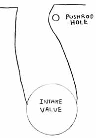
Figure 1 - Understanding the Intake Port
Terms and Definitions
Bowl: The
area below the valve seat (looks like a bowl!), sometimes
called the pocket.
Carbide bit: A cutting tool used for grinding metal- pretty
much a necessity for working on Ford exhaust ports.
Cartridge roll: A cylindrical sandpaper roll used on
grinding tools for porting. They come in different grits (roughness)
like regular sandpaper sheets.
Floor and Roof: With the head sitting as installed on
block, the bottom surface of the port is the floor and the
top surface is the roof.
Gasket match: Using an intake or exhaust gasket to create
marks around the port to use as a guide for increasing the
size of the port opening.
Port: This refers to the complete passage in the head
(intake or exhaust) from the mating surface to the valve head.
Sometimes will only refer to the opening in the mating surface.
Runner: Essentially the entire length of the port,
from opening to bowl.
Throat: The area just under the valve seat in the bowl.
It will typically have a sharp edge or lip left over from
machining of the seat.
Thermactor bump (air injection bump, smog bump): In
the exhaust ports of '68 and later heads there is a raised
portion in the roof with a small hole in it leading to the
air injection ports at the ends of the heads. I have seen
heads with the bump but no hole in it. Needless to say, this
bump is a BIG restriction.
Short turn radius: The part of the floor that turns
to the valve seat. In the intake port it has the shape of
a ski-jump.
Shrouding: When a valve is too close to a combustion
chamber wall or cylinder wall the air flow is impeded and
the valve is said to be shrouded.
Valve guide boss: The raised material that surrounds
the valve guide.
Venturi effect: The physical property of moving air
in a passage (pipe or port) increasing velocity as the diameter
of the passage decreases. A true venturi actually increases
in size after the restriction. Those cool velocity stacks
on multiple Weber carb intakes operate on this principle,
as do the boosters in Holley carburetors.
Intake
Ports
Lets start with some concepts before grabbing the grinder.
First, the Venturi effect. A true venturi is a short piece
of tube with a restriction in the middle that accelerates
the gas flowing through it. We are concerned with the change
in size, preferably big to small. The opposite happens if
you increase the size of the pipe or port, i.e. the flow velocity
decreases. So, if we look at the drawing of the intake port
cross section from the top, we see that the stock port is
smaller at the opening and larger at the valve head. The incursion
caused by the pushrod hole gives some venturi effect, but
is really too far from the valve to be helpful. By opening
up the port and cutting back the wall by the pushrod hole,
we can at least make the port straighter, if not truly taper
down, as it leads to the valve.
Once again, begin with scribing the gasket boundaries. Unfortunately
it is harder to align the intake gasket for marking the ports
since the bolts go in at an angle. The best way to determine
where an intake gasket will sit when the manifold is torqued
down, is to mock it up on the motor. Place the heads on the
block, secured with a couple of head bolts hand-tight. Then
lay the intake gaskets in place, don't use any sealer for
this mock up, and don't the cork end seals (you should never
use these anyway. Use silicone for the final installation.)
Lay the intake manifold down, and torque it to spec. You will
now be able to see the edge of the intake gasket stick up
along the head. Place a mark on the head to indicate the top
of the intake gasket. (It's also a good idea to note and mark
the position of the intake manifold at this time, so you can
gasket match it also.) Disassemble the mock up, and tape the
intake gasket to the head using the marks you made for alignment.
Then proceed to mark and scribe the gasket openings around
the ports. The Fel-Pro 1250's "Printoseal" is a
good template for the 289 and 5.0 (E7) heads, having dimensions
of 1.20"x2.00". For the 351 head, or for a larger
port, the Fel Pro 1262 offers 1.28"x2.10".
You should also check your intake manifold ports to be sure
they are not going to be larger than your head ports (not
likely with stock intakes, unless yours has been modified.)
That is the worst mismatch, since the air/fuel mixture coming
through the intake runner will hit the smaller head port.
The opposite effect, a smaller intake port leading to a larger
head port, is not a problem, and is in fact is how the intake
and heads come from the factory.
After marking you can begin grinding to match your template.
Keep the grinder moving up and down and in circles to ensure
smooth, flat walls. Take material off of the bump caused by
the pushrod hole. Use calipers to keep the width consistent
top to bottom and port to port. Clean out casting ridges as
far back as you can reach (the Dremel flex shaft tool works
well here.)
Once all eight port entries are finished you can move onto
the valve guide bosses. The intake valve guide boss stands
out at 90 degrees to the roof surface, has a flat top with
sharp edges, and is WAY too tall. Begin grinding the front
edge of the boss keeping in mind three goals:
1. You want to lay the front side back to about 45 degrees,
2. You want to decrease the height by at least ½,
3. The leading edge needs to be narrower than stock, but not sharp
edged, more like a neutral lift foil (think bottle nosed dolphin
or the leading edge of a sailboat keel.)
The short turn radius is another critical area. Again, you
don't want to change it's as-cast shape, just remove ridges
and any bumps. The turn allows the airflow to change direction
gradually as it turns to go out the valve. The idea of a ski-jump
is apt. If the radius is too small the flow will separate
at the valve seat and become very turbulent, reducing flow.
Professional porters can change this shape to improve flow,
but since we aren't professionals, our advice is to not change
its shape!
With the boss looking good the bowl is all that's left. Just
take out the sharp ridges and remove the bulge in the side
wall. Leave the intake surfaces at about an 80 grit finish.
It will help keep the fuel in suspension. There is really
no need to have a high polish in the intake port, it can actually
cause fuel puddling
Finally, the combustion chamber can be cleaned up with possibly
a little de-shrouding work. Looking at the diagram
of flow through the intake and you can see how the valve
head turns the flow to almost 90 degrees from its original
direction down the bowl. As the valve opens the flow is moving
out, towards the side of the combustion chamber, not down
into the cylinder. If the combustion chamber wall is too close
to the valve seat and standing up at 90 degrees from the chamber
floor, the flow hits the wall and literally "stacks-up" until
the valve is opened far enough for the flow to go past the
wall. If the valve is big enough and the cylinder bore small
enough, the cylinder wall itself will cause shrouding.Some
porters like to smooth the chamber to a mirror smooth finish,
others only to the same finish as the intake port. Removing
sharp edges will help reduce the chance of detonation. If
you want to try and open up the area around the intake valve
(good idea on early 289 heads w/ 54cc chambers) the technique
is to lay the wall back at a 45degree angle without changing
where it meets the chamber floor. Don't be too aggressive
in the combustion chamber, since any material you remove also
increases the volume of the combustion chamber, resulting
in lower compression. If you do extensive de-shrouding, be
sure to check the volume of each chamber to achieve consistancy.
|