| Part I: Shortblock
Assembly |
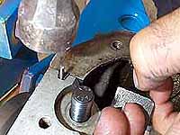
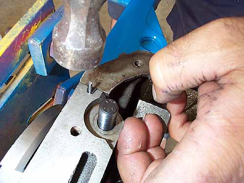
18. Finally, tap in the steel pins which serve to wedge
the side seals in place. |
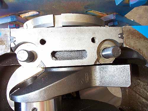
19. The rear main cap and bearing and seal installed.
The side seals and pins should be flush with the block and cap.
|
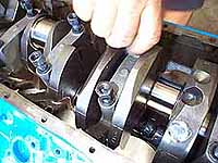
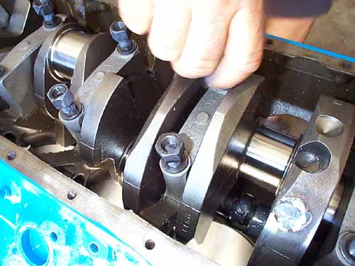
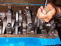
20. With the main bearings in the caps, place them in
their respective positions on the crank. Use the ARP moly lube
on the stud washers and nuts. |
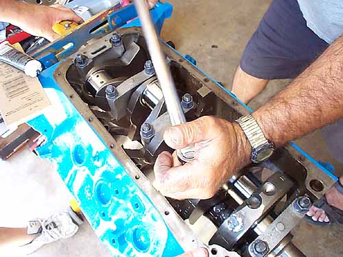
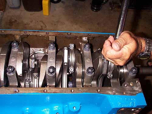
21. Torque the mains stud nuts to 90 lb.ft. when using
ARP moly (130 lb.ft. using 30W oil.) We recommend torquing in
two stages -first to 50 lb.ft. then to 90 lb.ft. |
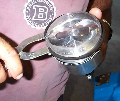
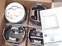
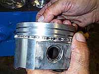
22. There is not much choice when it comes to FE
pistons. Other than these off-the-shelf Federal Mogul forged
pistons (0.030" over, floating wrist pins). If you need
high compression, your only option is to go with a custom set
from JE or the like. With our zero-decked block, and milling
the heads, we're expecting 11:1.
|
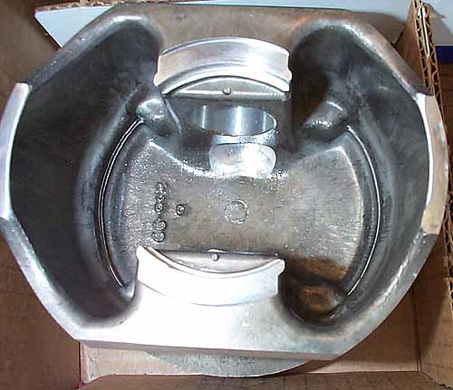
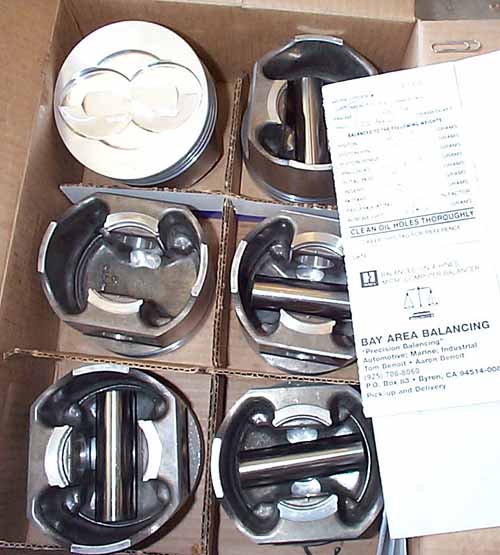
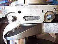
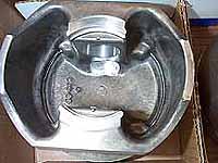
23. We had the entire rotating assembly balanced by the
machine shop. Typical procedure is to find the lightest piston
and rod in the set of eight, then match the others by removing
weight from the others. On piston weight is usually removed
by milling on the underside as shown here.
Once balanced, rods, pistons and pins are numbered and installed
in their respective cylinders. |
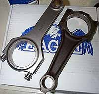
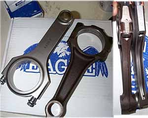
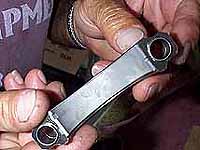
24. The stock rods could arguably handle 6500 rpm shifts,
with upgraded rod bolts, polished and shot peened beams, but
we opted for peace of mind with a set of steel Eagle rods. If
we plan to spray, these are a must. They are not cheap ($800),
but to condition the stockers would have cost about $200...and
still left something to be desired. |
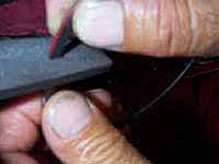
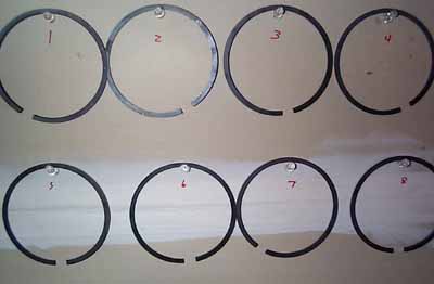
25. To seal the cylinders, we went with Speed Pro
plasma-moly faced rings.
As with most performance rings, they need to be file fit to
the block. Place a flat file in a vice, and file the ring
inside to out as shown. You can file one side of the ring,
or both (assuming both sides of your file are the same grain!)
The top rings are gapped to 0.020"
and the seconds to 0.014".
|
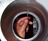
27. Check the gap using a feeler guage. It is best to
check the gap near the bottom of the bore, in case there is
any taper in the cylinder. |
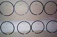
28. Once gapped, keep the rings organized to the
cylinder which they belong. Because of minor variations from
bore to bore, you don't want to gap all the rings to the same
size and install them randomly. |
 29.
With the pistons on the rods, the 29.
With the pistons on the rods, the
rings can go on. Place the expander ring on first, then the
top and bottom oil rings, by hand.
|
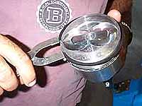
30. The second and top rings can go on next using
a ring spreader tool. |
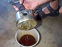
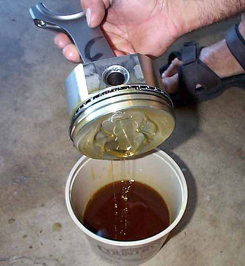
31. The pistons get dipped in a bucket of oil before
they go into the bores. |
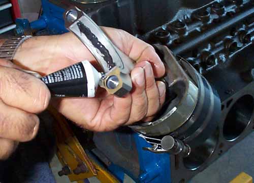
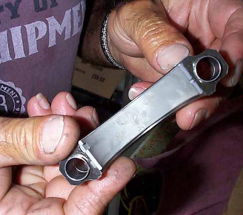
32. Install the rod bearing and use plenty of moly
on the crank mating side only.
When installing the rods make sure the tapered edge of the rod
corresponds to the tapered outer edge of the crank rod journal.
The flat, untapered, surface of the rod end faces towards the
center of the journal, against the other rod. |
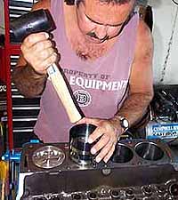
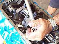
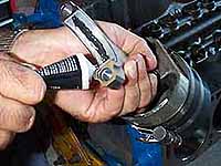
33. Victor knocks in the pistons using the handle
of a mallet. Go slow, you don't want to have a ring hang up
on the block and break or scratch the bore. It's also a good
idea to have someone guide the rod as it come down to prevent
nicking the crank journals.
Remember to put the rod/piston combo in the correct cylinder
in order to maintain the correct balance with the crankshaft.
|
34. Place the other half of the rod bearing in its shell,
be sure to line up the notches. |
35. Torque the rod cap screws to 63 lb.ft.
|
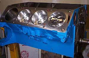
36.
The finished short block. In the next
part we'll finish up the long block and install the 428.
|
|
|