
Intake Manifold Selection and Preparation
In order to make the power we are after we need an intake
manifold
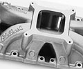
The Edelbrock Vic. Jr. single
plane intake.  |
capable of making power past
6500. At this rpm range we could still consider a dual-plane
manifold, such as a Weiand Stealth or Edelbrock RPM, however
because this engine is being built mainly for dragstrip
use, we were not concered with losing some low-end driveability.
Therefore we opted for the Edelbrock Victor Jr., pretty
much the gold standard when it comes to small block Ford
single plane intakes. While we will lose some driveability
and torque below 3000 rpm, we can be assured of sqeezing
the maximum power available from our head and cam combination.
The Victor Jr. was
also an intake we already owned, so it made sense to utilize
it rather than blow our budget on a new manifold. Unfortunately
however when we took a close
look at the intake alignment with our milled World Sr.
heads, we noticed the ports on the intake and those on
the heads did not line up too well. In other words, if
we looked down the intake runners we could see an uneven
transition from the intake port to head port. What we
could see was the some of the upper head mating surface
showing in the intake port. Consequently the floor of
the intake port was
higher than the floor of the head port, creating a "cliff".
This did not come as a surprise, considering that we had
milled the heads 0.030".
We visually examined the port alignment, and also used
a coat hanger, with a small bend at the tip, to probe
into the port and "feel" the drop between the
floor of the ports. Finally we use feeler gauges to measure
the gap at the end rails (distance between manifold and
block surface).
| |
|
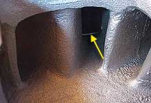
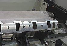
 There is no point in porting
heads, or even buying a set of decent flowing heads,
if you are going to throw it away on poor intake
alignment. The transition you see in the picture
not only reduces port volume, it creates poor flow
and turbulence.
There is no point in porting
heads, or even buying a set of decent flowing heads,
if you are going to throw it away on poor intake
alignment. The transition you see in the picture
not only reduces port volume, it creates poor flow
and turbulence. |
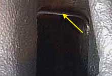
 Oddly enough, on one side
of the intake it was the floor transistion which
did not line up. However on the opposite side it
was the top of the port which was off. Either way
we needed to mill the intake to resolve the misalignment.
Oddly enough, on one side
of the intake it was the floor transistion which
did not line up. However on the opposite side it
was the top of the port which was off. Either way
we needed to mill the intake to resolve the misalignment. |
These steps gave us a good approximation that the intake
needed to be lowered
0.020". This would align the tops of the ports, with
a minor cliff remaining at the floor. We would then port
match the intake manifold and heads to obtain a perfect
alignment. To further confirm 0.020" would suffice,
we set the intake on the heads without any gaskets (Fel
Pro "Printoseal 1262 gasket is approximately 0.025"
when compressed.) Without the gaskets the alignment was
very close.
We
took our manifold to the PRI show in Sacramento, where
DCM had their latest and greatest computer controlled
milling and surfacing machine on display. The following
steps outline the process of properly aligning an intake
on the machining jig and then surfacing the mating surfaces.
| Milling the
Intake Manifold |
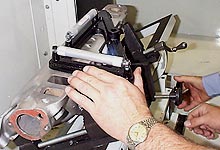
The intake is set on the mill and then leveled on
the X and Y axis to ensure the cut is made at exactly
90 degrees to the gasket surface. |
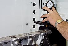
Interestingly our machinist detected 0.003"
twist in the surface near the water passages. The
hot coolant causing warpage is the cause. Since
were were taking 0.020" off per side, this
would set the surfaces true. |
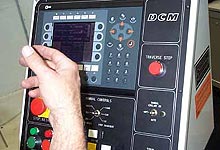
 Once they figured out how to mount the intake securely,
it was simply a matter of setting the parameters
in the computer, and sipping coffee while the mill
did it's job.
Once they figured out how to mount the intake securely,
it was simply a matter of setting the parameters
in the computer, and sipping coffee while the mill
did it's job. |
 The DCM surfacer cuts aluminum
at a blazing fast 12-14 inches per minutes. All
it took was two passes and a couple minutes and
we were on our way with a corrected manifold.
The DCM surfacer cuts aluminum
at a blazing fast 12-14 inches per minutes. All
it took was two passes and a couple minutes and
we were on our way with a corrected manifold. |
We did quite a bit of research
trying to find a "formula" for milling intake
manifolds, and the conclusion is that there is none. It
would be nice to say that if you mill the heads 0.030,
you mill the intake 0.015 per side. However because most
intakes and heads aren't perfectly aligned to begin with,
this formula would still leave you with poor alignment.
Another thing to consider is that obtaining perfect alignment
is much easier with a single plane manifold because you
can actually see the transition on four of the eight runners.
On a dual plane intake this is impossible, and you must
resort to using a coat hanger to feel the transition.
We surmise that most people who have milled heads or decks,
or have swapped on an aftermarket manifold or heads, have
an alignment problem. It is worth checking out and resolving. |
 (Final Block Assembly)
 |
| |
|
|
|
|
|


