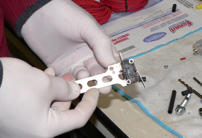
The included WOT throttle switch uses the same type of
bracket used for mounting the fuel and nitrous solenoids.
The included WOT throttle switch uses the same type of
bracket used for mounting the fuel and nitrous solenoids. |
|
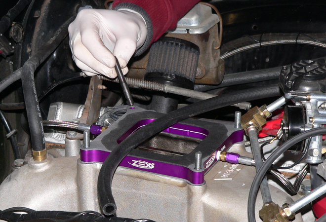
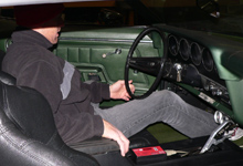
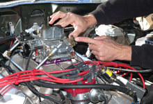
 I planned to mount the WOT switch and bracket on the rear
driver's side carburetor stud. Turns out I needed a longer
stud to make it work. I pulled the carb and added a single
1-1/2" carb stud in this location.
I planned to mount the WOT switch and bracket on the rear
driver's side carburetor stud. Turns out I needed a longer
stud to make it work. I pulled the carb and added a single
1-1/2" carb stud in this location. |
| |
|
|

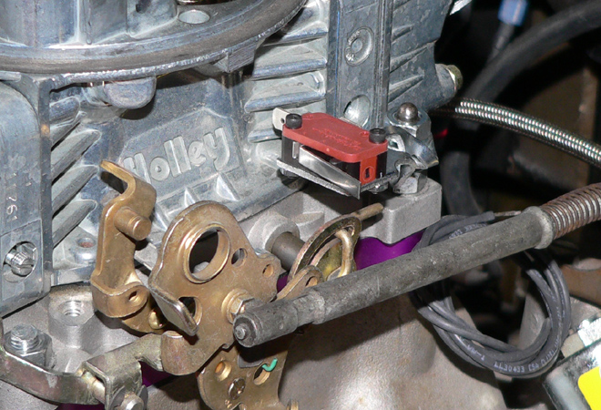
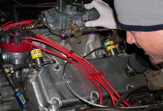
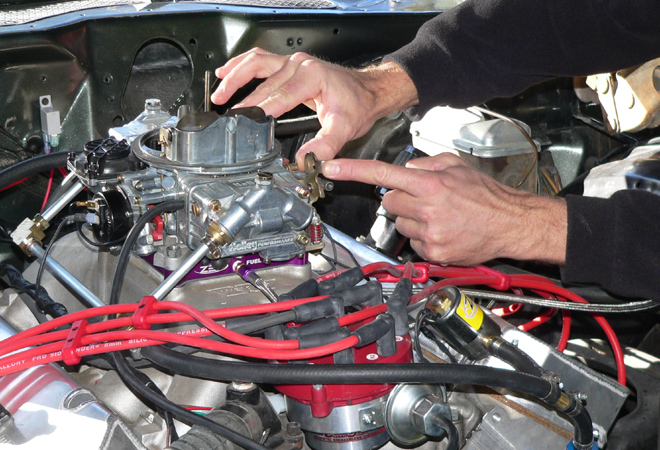
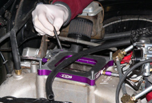
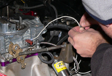
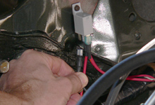
 It wasn't pretty but it was solid. The bracket required
a good twist and turn to work. You can see that at WOT,
the carb linkage would make contact with the WOT switch
arm.
It wasn't pretty but it was solid. The bracket required
a good twist and turn to work. You can see that at WOT,
the carb linkage would make contact with the WOT switch
arm. |
|
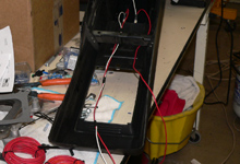
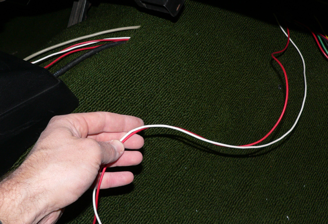
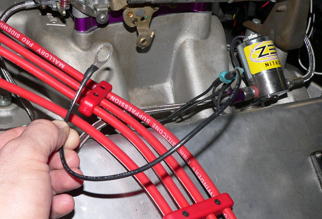
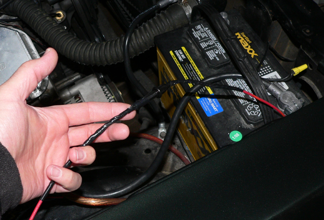
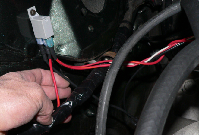
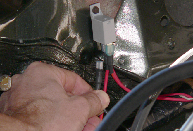
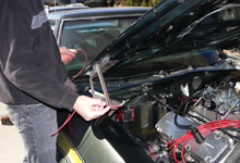
 Remember this shot from the bottle heater section? The
paired red and white wire from the primary arming switch
would come into play now.
Remember this shot from the bottle heater section? The
paired red and white wire from the primary arming switch
would come into play now. |
| |
|
|
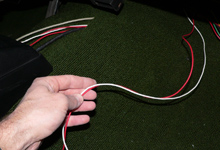
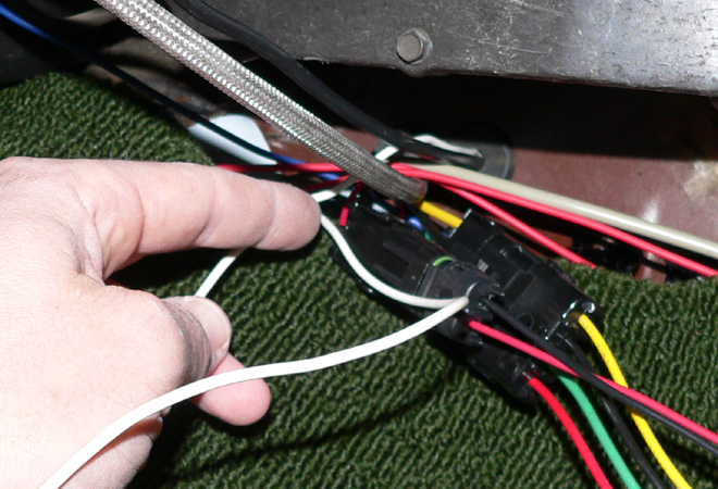
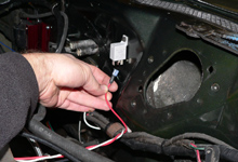
 Here's the pair routed from the console and just above
the passenger floor board.
Here's the pair routed from the console and just above
the passenger floor board. |
|
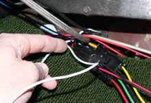
 I threaded the white wire through the firewall and headed
for the WOT switch.
I threaded the white wire through the firewall and headed
for the WOT switch. |
| |
|
|
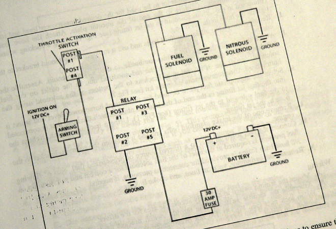
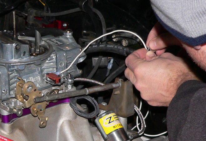
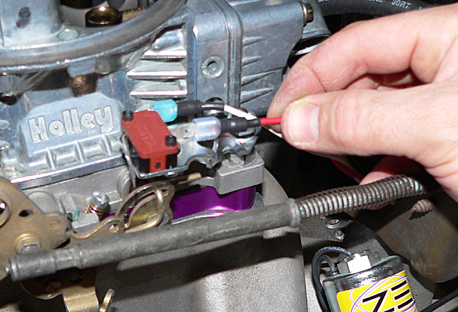
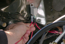
 This shot shows the white wire from the primary arming
switch attached to "Post 4" on the WOT switch.
The
red wire from the primary arming switch was connected
to a 12V Key On terminal on my auxiliary terminal block.
This shot shows the white wire from the primary arming
switch attached to "Post 4" on the WOT switch.
The
red wire from the primary arming switch was connected
to a 12V Key On terminal on my auxiliary terminal block. |
|

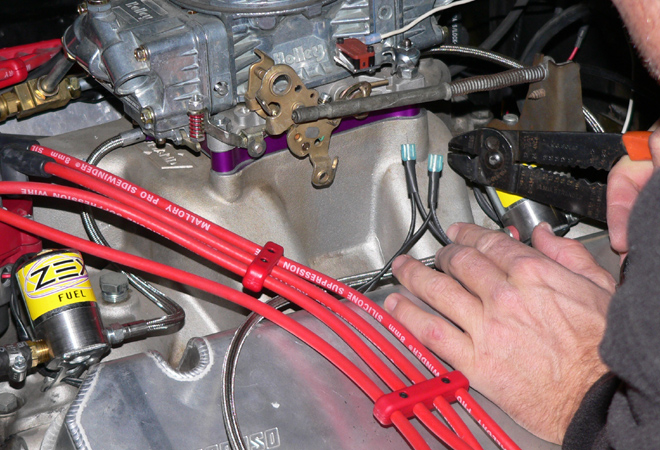
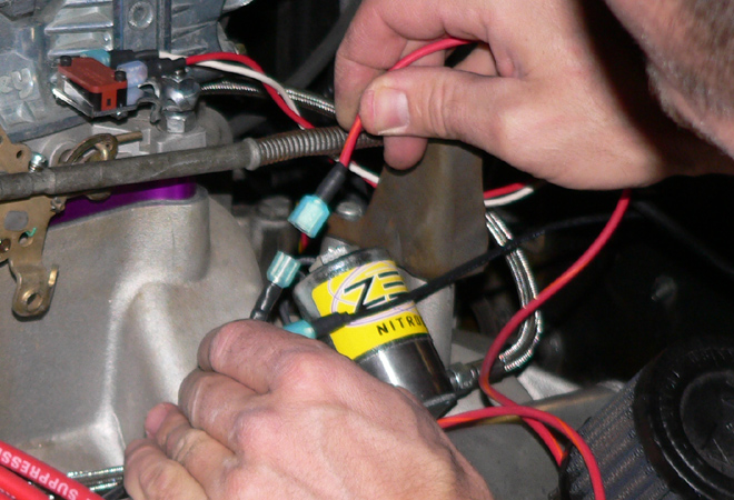
 Now it was time to wire the fuel and nitrous solenoids.
Neither solenoid had specific polarity. Either wire on
each solenoid can serve as that solenoid's ground wire.
Now it was time to wire the fuel and nitrous solenoids.
Neither solenoid had specific polarity. Either wire on
each solenoid can serve as that solenoid's ground wire. |
| |
|
|

 I joined one wire from each solenoid together with a single
wire and ring terminal for grounding on the engine block.
I joined one wire from each solenoid together with a single
wire and ring terminal for grounding on the engine block. |
|

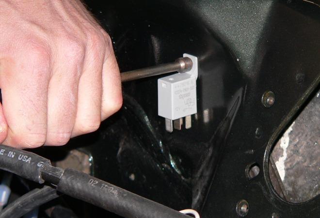
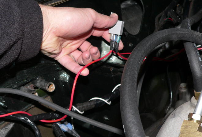
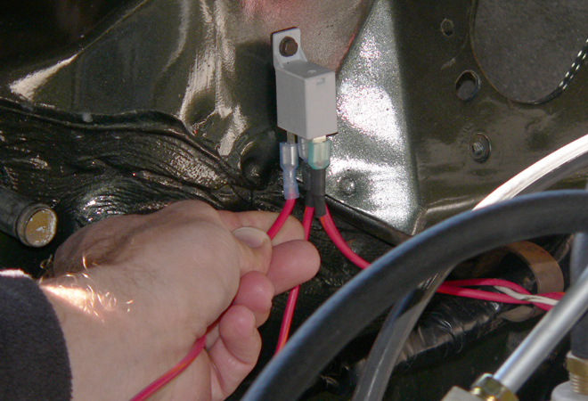
 Here I found a suitable firewall location for the included
and necessary relay.
Here I found a suitable firewall location for the included
and necessary relay. |
| |
|
|

 I made up this red wire to run from "Post 1"
on the WOT switch...
I made up this red wire to run from "Post 1"
on the WOT switch... |
|
 ...to "Post 1" on the relay.
 |
| |
|
|

 Next, I joined the two remaining solenoid wires for a
run to "Post 3" on the relay.
Next, I joined the two remaining solenoid wires for a
run to "Post 3" on the relay. |
|

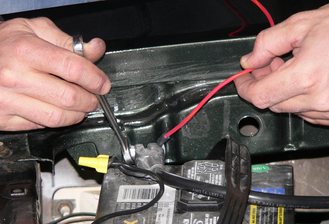
 The relay needed 12V straight from the battery.
 |
| |
|
|
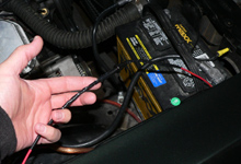
 That same 12V wire required a 30 amp fuse.
 |
|

 The now fused 12V battery wire was connected to "Post
5" on the relay.
The now fused 12V battery wire was connected to "Post
5" on the relay. |
| |
|
|
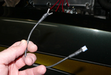
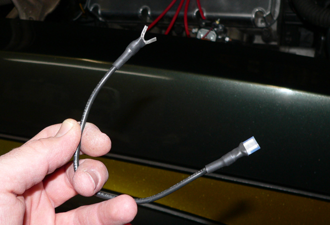
 I made up a ground wire for the relay...
 |
|

 ...and connected it to "Post 2" on the relay.
I used the same engine block ground location that I used
for grounding the solenoids.
...and connected it to "Post 2" on the relay.
I used the same engine block ground location that I used
for grounding the solenoids. |
| |
|
|
 With basic wiring done, it was time to test the solenoids.
Agani, no need for the nitrous bottle to be opened or
the car to be running.
With basic wiring done, it was time to test the solenoids.
Agani, no need for the nitrous bottle to be opened or
the car to be running. |
|

 With the key in the on position and the primary arming
switch on, I manually depressed the WOT switch and confirmed
that both solenoids opened up. The "click" was
easily identifiable.
With the key in the on position and the primary arming
switch on, I manually depressed the WOT switch and confirmed
that both solenoids opened up. The "click" was
easily identifiable. |

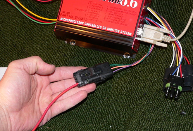
The Mallory box specifies this violet wire originating
from the connector shown as the RPM window switch wire.
The Mallory box is a "ground" based system.
This means, the switch is active when it is grounded.
Confusing? Let's show you how easy it is. |
|
I temporarily ran this long red wire (the one I connected
to the violet wire in caption 1) outside the car and toward
the firewall mounted relay I worked with in the previous
wiring section. |
| |
|
|
I pulled the relay grounding wire from "Post 2"
that I had made up in the previous wiring section... |
|
...and simply replaced it with the single RPM window switch
wire from the Mallory HyFire ignition box. |
| |
|
|

For testing purposed, I set the RPM window switch to activate
a 1500RPM and shut off at 2000RPM. |
|
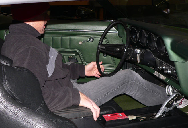
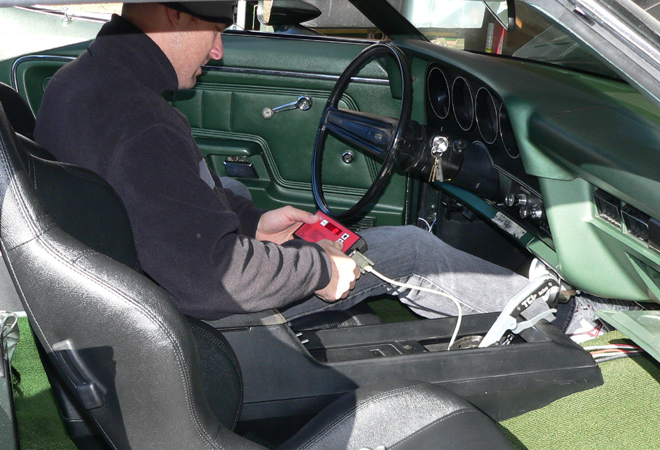
With the motor running, I slowly ran the throttle from
idle to 2500 RPM while manually depressing the WOT switch.
I clearly heard two clicks, the sign of a safe nitrous
system. |