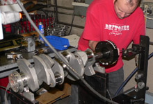
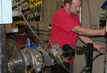
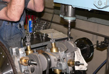
 The crank is placed in the saddle and the harmonic balancer
is fitted. A magnetic probe from the Hines machine is
attached to the balancer at the crankshaft centerline.
The crank is placed in the saddle and the harmonic balancer
is fitted. A magnetic probe from the Hines machine is
attached to the balancer at the crankshaft centerline. |
|
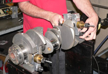
 The bob weights are clamped in place on by one.
 |
| |
|
|
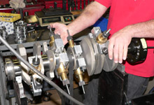
 With all four bob weights
in place on each rod journal, the crank is test spun by
hand.
With all four bob weights
in place on each rod journal, the crank is test spun by
hand.
|
|
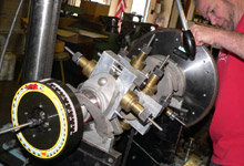
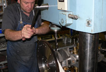
 The flywheel is fitted next. We used a Centerforce steel
flywheel.
The flywheel is fitted next. We used a Centerforce steel
flywheel. |
| |
|
|
 The balancing machine is turned on and the rotating assembly
is taken up to 500 RPMs.
The balancing machine is turned on and the rotating assembly
is taken up to 500 RPMs. |
|
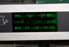
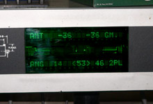
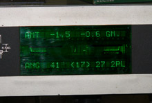
 A bit confusing at first but this display is actually
very simple. In our case it's telling us that 69 grams
of material needs to be removed from the front of the
crank (balancer end) at angle 13. It also tells us that
79 grams of material needs to be removed from the rear
of the crank (flywheel end) at angle 45. The number between
the carats <45> is the angle the crank is currently
situated at.
A bit confusing at first but this display is actually
very simple. In our case it's telling us that 69 grams
of material needs to be removed from the front of the
crank (balancer end) at angle 13. It also tells us that
79 grams of material needs to be removed from the rear
of the crank (flywheel end) at angle 45. The number between
the carats <45> is the angle the crank is currently
situated at. |
| |
|
|
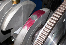
 You can see here that the factory already removed material
during the OE balancing process. See the bore in the frontmost
counterweight.
You can see here that the factory already removed material
during the OE balancing process. See the bore in the frontmost
counterweight. |
|
 And this is the existing bore left in the rearmost counterweight
from the factory.
And this is the existing bore left in the rearmost counterweight
from the factory. |
| |
|
|
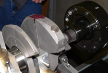
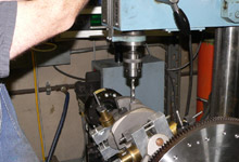
 This press is an integral part of the balancing machine.
Here it is slid into position to begin the incremental
process of removing material from angle 13 on the frontmost
counterweight.
This press is an integral part of the balancing machine.
Here it is slid into position to begin the incremental
process of removing material from angle 13 on the frontmost
counterweight. |
|
 The press in slid to the rear of the crankshaft and material
is removed from the rearmost counterweight at angle 45.
The press in slid to the rear of the crankshaft and material
is removed from the rearmost counterweight at angle 45. |
| |
|
|
 Of course it is best to work incrementally. Adding material
to a crankshaft is costly and more time consuming. You
can see that the first round of material removal brought
us halfway there.
Of course it is best to work incrementally. Adding material
to a crankshaft is costly and more time consuming. You
can see that the first round of material removal brought
us halfway there. |
|
 The intent is to creep up on zero. A smaller bit is swapped
into place and work begins on a smaller counterweight
up front.
The intent is to creep up on zero. A smaller bit is swapped
into place and work begins on a smaller counterweight
up front. |
| |
|
|
 This Hines balancer begins flashing "OK" once
the crank is balanced within 10 grams. Of course that's
just not good enough for everybody, so Augie at Superior
Machine takes our 400's crank in real close.
This Hines balancer begins flashing "OK" once
the crank is balanced within 10 grams. Of course that's
just not good enough for everybody, so Augie at Superior
Machine takes our 400's crank in real close. |
|
|
| |
|
|
 (Balancing
the Pressure Plate) (Balancing
the Pressure Plate) |
| |


