
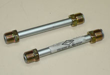
 We started by purchasing three 12" segments of 3/8"
steel brake tubing from our local automotive chain store.
Next, we special ordered from www.hoseandfittings.com
a 3/8" inverted flare "tee" (part no. HF244IFD-06-06-06)
and a 3/8" inverted flare "elbow" (part
no. HF255IFHD-06).
We started by purchasing three 12" segments of 3/8"
steel brake tubing from our local automotive chain store.
Next, we special ordered from www.hoseandfittings.com
a 3/8" inverted flare "tee" (part no. HF244IFD-06-06-06)
and a 3/8" inverted flare "elbow" (part
no. HF255IFHD-06). |
|
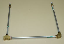
 By connecting the brass fittings and steel tubing, we
envisioned the finished product. Obviously, we needed
to shorten the primary and secondary legs as well as our
connecting line to match our carburetor's distance between
centers. This meant we'd be making a new flare on one
end of all three lines.
By connecting the brass fittings and steel tubing, we
envisioned the finished product. Obviously, we needed
to shorten the primary and secondary legs as well as our
connecting line to match our carburetor's distance between
centers. This meant we'd be making a new flare on one
end of all three lines. |
| |
|
|
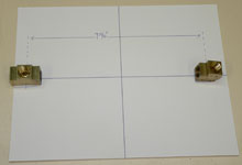
 We started with the connecting line since we already knew
our Holley 4150 had a distance between centers of 9-7/16".
We made a diagram and outlined the required positions
of the brass tee and elbow so not to make any mistakes.
We started with the connecting line since we already knew
our Holley 4150 had a distance between centers of 9-7/16".
We made a diagram and outlined the required positions
of the brass tee and elbow so not to make any mistakes. |
|
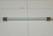
 By laying one of the 12" steel lines on top of our
diagram and "screwing" each fitting from the
tubing into our virtual brass tee and elbow, we could
determine a proper cut line.
By laying one of the 12" steel lines on top of our
diagram and "screwing" each fitting from the
tubing into our virtual brass tee and elbow, we could
determine a proper cut line. |
| |
|
|
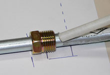
 Here you'll notice the line fitting is showing two threads
outside the virtual fitting. This was determined by noting
how many threads were outside the brass fitting during
a trial fit. We placed a mark on the tubing about 1/8"
ahead of the fitting to account for the roll of the flare.
Here you'll notice the line fitting is showing two threads
outside the virtual fitting. This was determined by noting
how many threads were outside the brass fitting during
a trial fit. We placed a mark on the tubing about 1/8"
ahead of the fitting to account for the roll of the flare. |
|
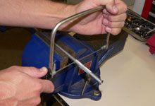
 Using a coping saw with a blade suited for cutting metal,
we shortened the line. A band saw or miter saw with a
carbide blade can help achieve a more exact first cut.
Using a coping saw with a blade suited for cutting metal,
we shortened the line. A band saw or miter saw with a
carbide blade can help achieve a more exact first cut. |
| |
|
|
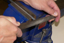
 Since we used the coping saw, the cut was not perfectly
square. To make a good flare the cut needs to be perfect,
we used a file to get there.
Since we used the coping saw, the cut was not perfectly
square. To make a good flare the cut needs to be perfect,
we used a file to get there. |
|
 Following Tom Zuloaga's advice for achieving quality flares,
we used a drill bit to remove any burrs from inside the
tubing.
Following Tom Zuloaga's advice for achieving quality flares,
we used a drill bit to remove any burrs from inside the
tubing. |
| |
|
|
 Before we made the flare we made sure both fittings were
still on the tubing. It can be heartbreaking when you
make a flare while your fitting is still on the work bench.
Before we made the flare we made sure both fittings were
still on the tubing. It can be heartbreaking when you
make a flare while your fitting is still on the work bench. |
|
 Now that the connecting line was the proper length, we
connected it to the brass tee and the elbow.
Now that the connecting line was the proper length, we
connected it to the brass tee and the elbow. |
| |
|
|
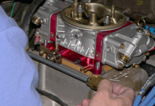
 With the carburetor on the intake, we envisioned the best
location for the line as it hung off the carb. The concern
here being interference with the manifold.
With the carburetor on the intake, we envisioned the best
location for the line as it hung off the carb. The concern
here being interference with the manifold. |
|
 Using our imagination, we got an idea of how long our
primary and secondary tubing should be.
Using our imagination, we got an idea of how long our
primary and secondary tubing should be. |
| |
|
|
 Determining where to cut the primary and secondary tubing
was not as critical as determining where to cut the connecting
line.
Determining where to cut the primary and secondary tubing
was not as critical as determining where to cut the connecting
line. |
|
 After cutting, filing, de-burring, and flaring the primary
and secondary lines, they were ready to be attached to
the brass tee and elbow.
After cutting, filing, de-burring, and flaring the primary
and secondary lines, they were ready to be attached to
the brass tee and elbow. |
| |
|
|

 We loosely connected the line to the carburetor.
 |
|
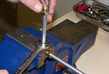
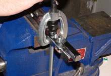
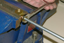
 Confident about the fit, we tightened down each fitting
with the use of a vise.
Confident about the fit, we tightened down each fitting
with the use of a vise. |
| |
|
|
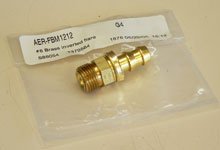
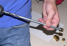
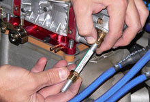
 In order to attach 3/8" rubber fuel line, we needed
a 3/8" inverted flare-to-3/8" hose barb fitting.
We grabbed the Aeroquip piece (AER-FBM1212) from Summit.
In order to attach 3/8" rubber fuel line, we needed
a 3/8" inverted flare-to-3/8" hose barb fitting.
We grabbed the Aeroquip piece (AER-FBM1212) from Summit. |
|

 We attached the hose barb fitting to the line.
 |
| |
|
|
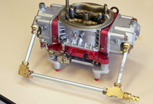
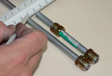
 Here's a picture of the final product. On a side note,
the brass elbow fitting could have been eliminated if
we used a longer segment of brake tubing and made a 90
degree bend to connect with the brass tee.
Here's a picture of the final product. On a side note,
the brass elbow fitting could have been eliminated if
we used a longer segment of brake tubing and made a 90
degree bend to connect with the brass tee. |
|
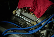
 Finally, we installed the carburetor
and tested for leaks. There were none. A look back into
a dark garage was a proud moment.
Finally, we installed the carburetor
and tested for leaks. There were none. A look back into
a dark garage was a proud moment. |


