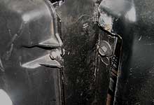
 We cut down the radiator
flanges so the unit could fit behind the core support
mounting tabs. We fabricated two brackets to secure
the radiator in its new location.
We cut down the radiator
flanges so the unit could fit behind the core support
mounting tabs. We fabricated two brackets to secure
the radiator in its new location. |
|
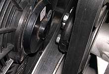
 By moving the radiator back
we gained a comfortable 1/2" between the fan
motor and blower pulley. We may have been able to
find a thinner fan, but this modification spares
us the expense.
By moving the radiator back
we gained a comfortable 1/2" between the fan
motor and blower pulley. We may have been able to
find a thinner fan, but this modification spares
us the expense. |
| |
|
|
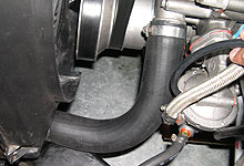
 We politely asked our neighborhood parts store manager
if we could browse the radiator hose aisle. Five
minutes later we came up with the perfect pre-moulded
hose to connect our water pump and radiator. We
haven't a clue what the original application is.
A tip - bend a coat hanger into the shape and length
you need and take it with you to ease finding the
right hose.
We politely asked our neighborhood parts store manager
if we could browse the radiator hose aisle. Five
minutes later we came up with the perfect pre-moulded
hose to connect our water pump and radiator. We
haven't a clue what the original application is.
A tip - bend a coat hanger into the shape and length
you need and take it with you to ease finding the
right hose. |
|
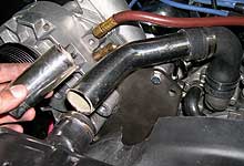
 The chrome upper radiator hose included in the 87-93
5.0L Vortech kit will actually fit our needs just
fine once a few inches is hacked off. As mentioned
in Part I, we replaced the early style thermostat
housing with a 5.0L 90-degree style to allow the
hose to clear the supercharger bracket.
The chrome upper radiator hose included in the 87-93
5.0L Vortech kit will actually fit our needs just
fine once a few inches is hacked off. As mentioned
in Part I, we replaced the early style thermostat
housing with a 5.0L 90-degree style to allow the
hose to clear the supercharger bracket. |
| |
|
|
| |
Boost
Referenced Fuel Pump
Perhaps the most critical area of any power
adder installation is addressing the fuel system.
There are two factors to consider; volume and pressure.
We first need to obtain a pump capable of supplying
adequate volume for the gross horsepower our engine
will make. To properly come up with this figure
requires a good estimate of the power the engine
will make, the efficiency of the engine or BSFC
(Brake Specific Fuel Consumption), and the pressures
at which the pump will operate. We did not spend
the time calculating these numbers. We simply purchased
the highest flowing Carter mechanical pump we could
find (120 gallons per hour at 8 psi) and modified
it to work under boost. On a super or turbo charged
engine the fuel pressure must rise proportional
to boost, otherwise the increase in pressure will
prevent fuel from entering the carburetor bowls.
To perform this modification we simply reference
a mechanical fuel pump diaphragm to boost pressure
as outlined below. This is a very simple way to
setup a fuel system on a carbureted supercharged
engine. It will support around 550 horsepower and
10-12 lbs. of boost pressure. Any more than that
and you must step up to a high pressure and volume
electrical pump. These are considerably more difficult
to setup as you need a return/bypass line from the
pump back to the fuel tank, as well as a boost referenced
pressure regulator.
|
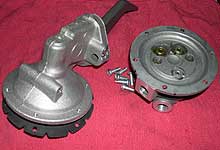
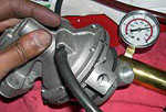
We'll modify this Carter
120gph mechanical pump so it puts out pressure proportional
to boost. Note the pump comes with a vent hole which
allows the inside of the pump to equalize to atmospheric
pressure. |
|
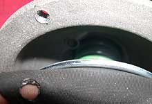
Peeking behind the diaphragm
reveals the port hole to atmosphere. If we attach
a vacuum line connected to the carb inlet the pump
will pressurize in reference to boost pressure. |
| |
|
|
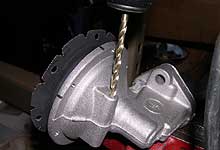
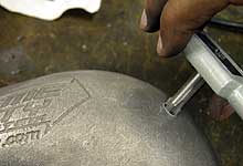
We drilled through the opposite
side of the boss to make attaching the vacuum line
easier. We'll plug the factory hole on the other
side. |
|
We pressed in a brass vacuum
nipple as shown. |
| |
|
|
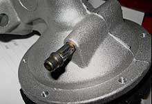
 The pump is reassembled and
checked for leaks by applying vacuum. This effectively
simulates boost pressure.
The pump is reassembled and
checked for leaks by applying vacuum. This effectively
simulates boost pressure. |
|
 Next will drill and tap our
carb hat so the pump is referenced to boost pressure.
We do not want to attach the fuel pump to the an
intake vacuum source.
Next will drill and tap our
carb hat so the pump is referenced to boost pressure.
We do not want to attach the fuel pump to the an
intake vacuum source. |
| |
|
|
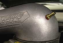
 Using silicone sealer we
secure the hose barb to the carb hat.
Using silicone sealer we
secure the hose barb to the carb hat. |
|
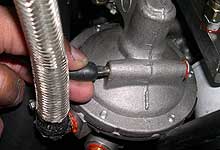
 The vacuum line connects
the carb hat to the fuel pump. The pump will now
increase pressure 1 psi per 1 lb. of boost above
the base pressure of 8psi. So with 6 lbs of boost
we should see 14 psi of fuel pressure. We are not
using a regulator.
The vacuum line connects
the carb hat to the fuel pump. The pump will now
increase pressure 1 psi per 1 lb. of boost above
the base pressure of 8psi. So with 6 lbs of boost
we should see 14 psi of fuel pressure. We are not
using a regulator. |


