 We're installing the Powetrax No-Slip locker on
this '66 Mustang, previously equipped with a spool.
The spool was horrendous for street driving, but
the only hope for traction behind the torquey 351W
motor.
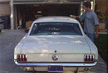
We're installing the Powetrax No-Slip locker on
this '66 Mustang, previously equipped with a spool.
The spool was horrendous for street driving, but
the only hope for traction behind the torquey 351W
motor. |
|
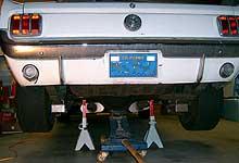
 Raise the vehicle and support the rear axle with
jack stands. Remove the driveshaft and axles. The
axles may require an axle puller, or a cheap trick
is to turn the drum around and secure it loosely
to the axle studs with a few lug nuts, then pull
sharply.
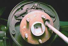
Raise the vehicle and support the rear axle with
jack stands. Remove the driveshaft and axles. The
axles may require an axle puller, or a cheap trick
is to turn the drum around and secure it loosely
to the axle studs with a few lug nuts, then pull
sharply. |
| |
|
|
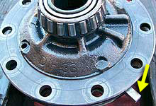
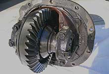
 The eight - inch Ford differential is not nearly
as famous as it nine-inch big brother, but when
built properly, with upgraded gears, axles, and
Powertrax, it can handle a motor with 400 lb. ft.
of torque without issue.
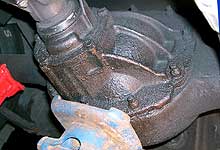
The eight - inch Ford differential is not nearly
as famous as it nine-inch big brother, but when
built properly, with upgraded gears, axles, and
Powertrax, it can handle a motor with 400 lb. ft.
of torque without issue. |
|
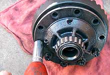
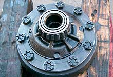
 Unbolt the ten differential mounting nuts and carefully
remove the housing assembly from the axle housing.
Our unit had been upgraded a while back with Richmond
3.80:1 gears and new bearings. If your unit is stock,
now is the time to consider a rebuild
Unbolt the ten differential mounting nuts and carefully
remove the housing assembly from the axle housing.
Our unit had been upgraded a while back with Richmond
3.80:1 gears and new bearings. If your unit is stock,
now is the time to consider a rebuild |
| |
|
|
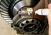
 Prior to removing the differential we mark the bearing
caps relative to their saddles. This ensure everything
goes back to their original positions, so as not
to change bearing preload or wear patterns.
Prior to removing the differential we mark the bearing
caps relative to their saddles. This ensure everything
goes back to their original positions, so as not
to change bearing preload or wear patterns. |
|
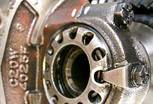
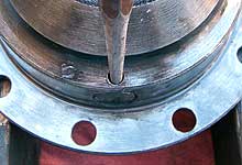
 We also mark the position of the bearing adjuster
relative to the lock. When removing the retainer
be sure to count the number of revolutions it
takes to back it out completely. This will ensure
it is installed back to the same position
We also mark the position of the bearing adjuster
relative to the lock. When removing the retainer
be sure to count the number of revolutions it
takes to back it out completely. This will ensure
it is installed back to the same position
|
| |
|
|
 With everything properly marked, we can remove the
bearing cap bolts and lift the case out of the housing.
It's not necessary to remove the adjuster and lock
as it will come apart once the cap is removed.
With everything properly marked, we can remove the
bearing cap bolts and lift the case out of the housing.
It's not necessary to remove the adjuster and lock
as it will come apart once the cap is removed. |
|
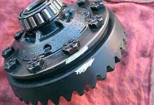
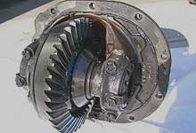
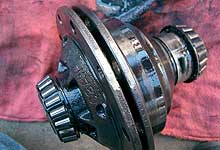
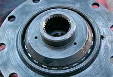
 Shown is the case and ring gear assembly removed
from the 8" housing. Scribe or paint a mark
on the ring gear relative to the deferential as
shown. This will ensure the gear is installed back
in the same position.
Shown is the case and ring gear assembly removed
from the 8" housing. Scribe or paint a mark
on the ring gear relative to the deferential as
shown. This will ensure the gear is installed back
in the same position. |
| |
|
|
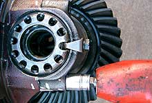
 An impact wrench makes easy work of removing the
ten ring gear mounting bolts.
An impact wrench makes easy work of removing the
ten ring gear mounting bolts. |
|
 With the ring gear off use a punch to knock the
roll-pin through the case. The roll pin goes through
the long shaft and other half of the differential,
serving to keep everything aligned.
With the ring gear off use a punch to knock the
roll-pin through the case. The roll pin goes through
the long shaft and other half of the differential,
serving to keep everything aligned. |
| |
|
|
 With the roll pin removed, the case halves can be
split apart. This may require careful prying with
a chisel or flat-blade screw driver. Note the smaller
half (left in the photo) is the cap, and the larger
half contains the assembly.
With the roll pin removed, the case halves can be
split apart. This may require careful prying with
a chisel or flat-blade screw driver. Note the smaller
half (left in the photo) is the cap, and the larger
half contains the assembly. |
|

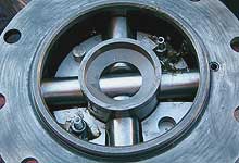
 Knock the long shaft through the case and remove
the guts. In our case there is a mini-spool. However,
a stock "open" differential would contain
a pair of spider and side gears, along with half
shafts.
Knock the long shaft through the case and remove
the guts. In our case there is a mini-spool. However,
a stock "open" differential would contain
a pair of spider and side gears, along with half
shafts. |
| |
|
|
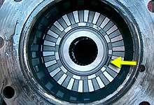
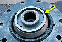
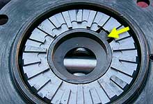
 After cleaning out the inside of the case place
the Powertrax coupler in the case as shown. Ensure
the gaps in the synchro ring align with the gaps
in the synchro teeth (arrow.) The synchro ring can
be moved by placing the coupler in a vise and using
the driver block to twist the ring into the desired
position.
After cleaning out the inside of the case place
the Powertrax coupler in the case as shown. Ensure
the gaps in the synchro ring align with the gaps
in the synchro teeth (arrow.) The synchro ring can
be moved by placing the coupler in a vise and using
the driver block to twist the ring into the desired
position. |
|

 The Powertrax driver block is then placed on top
of the coupler as shown here. The paddle tab must
sit in the paddle gap in the synchro (arrow).
The Powertrax driver block is then placed on top
of the coupler as shown here. The paddle tab must
sit in the paddle gap in the synchro (arrow). |
| |
|
|
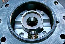
 Before proceeding we need to check for adequate
clearances using the supplied ring and block gauges.
Place the remaining driver and coupler into the
case, then set the ring gauge on the coupler as shown
here (arrow).
Before proceeding we need to check for adequate
clearances using the supplied ring and block gauges.
Place the remaining driver and coupler into the
case, then set the ring gauge on the coupler as shown
here (arrow). |
|
 Set the cap on top of the assembly without installing
the ring or ring bolts. Check for clearance between
the two halves using the provided block gauge (arrow).
The narrow side should fit, however when turned
to the wider side, it should not. If this does not
pass you must contact Powertrax.
Set the cap on top of the assembly without installing
the ring or ring bolts. Check for clearance between
the two halves using the provided block gauge (arrow).
The narrow side should fit, however when turned
to the wider side, it should not. If this does not
pass you must contact Powertrax. |
| |
|
|
 If the clearances are ok, remove the cap, driver
and coupler and continue with assembly. Place one
of the two supplied drivers over the block and on
the coupler as seen in this photo. Ensure the teeth
are fully engaugeed.
If the clearances are ok, remove the cap, driver
and coupler and continue with assembly. Place one
of the two supplied drivers over the block and on
the coupler as seen in this photo. Ensure the teeth
are fully engaugeed. |
|
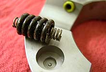
 Detail image shows proper placement of spring in
the driver. Install the four saddle springs (green)
as shown. Assemble the inner and outer springs (two
pair) and place into the recessed seats. Use heavy
bearing or axle grease on all springs.
Detail image shows proper placement of spring in
the driver. Install the four saddle springs (green)
as shown. Assemble the inner and outer springs (two
pair) and place into the recessed seats. Use heavy
bearing or axle grease on all springs. |
| |
|
|
 Install the long pinion shaft through the case and
block. Due to tight tolerances it may help to freeze
the pin overnight. Use a twisting motion while inserting
to help move past the saddle springs. Then install
the two short shafts.
Install the long pinion shaft through the case and
block. Due to tight tolerances it may help to freeze
the pin overnight. Use a twisting motion while inserting
to help move past the saddle springs. Then install
the two short shafts. |
|
 Install the second driver into the case. The notch
in the driver must line up with the paddle on the
driver block (arrow.)
Install the second driver into the case. The notch
in the driver must line up with the paddle on the
driver block (arrow.) |
| |
|
|
 Install the second coupler. A with the first, the
paddle opening must align with the paddle and notch
in the driver, as indicated in the previous step.
Install the second coupler. A with the first, the
paddle opening must align with the paddle and notch
in the driver, as indicated in the previous step. |
|
 Place the top halve of the case ont on to the bottom
halve. Reinstall the roll pin. Then secure the ring
gear to it's original location and torque bolts
evenly to 65-80 ft-lbs.
Place the top halve of the case ont on to the bottom
halve. Reinstall the roll pin. Then secure the ring
gear to it's original location and torque bolts
evenly to 65-80 ft-lbs. |
| |
|
|
 Install the case back into the housing. Be sure
to install the bearing caps (torque to 70-80 ft-lbs.),
and turn the adjusters in the number of revolutions
counted during disassembly. Our 8" third member
is now ready to be installed. We recommend using
silicone sealer rather than a gasket on the housing,
and new nuts and lock washers. Torque the third-member
nuts to 40 ft lbs.
Install the case back into the housing. Be sure
to install the bearing caps (torque to 70-80 ft-lbs.),
and turn the adjusters in the number of revolutions
counted during disassembly. Our 8" third member
is now ready to be installed. We recommend using
silicone sealer rather than a gasket on the housing,
and new nuts and lock washers. Torque the third-member
nuts to 40 ft lbs. |
|
 Before filling the case with gear oil we can test
for proper operation. With the transmission in park
or in gear hold one wheel forward against the driveline.
A helper should not be able to rotate the other
wheel in the same direction. It should however move
freely in the reverse direction. Repeat this test
for both sides. If the test passes fill the case
with 75W-140 gear oil and road test.
Before filling the case with gear oil we can test
for proper operation. With the transmission in park
or in gear hold one wheel forward against the driveline.
A helper should not be able to rotate the other
wheel in the same direction. It should however move
freely in the reverse direction. Repeat this test
for both sides. If the test passes fill the case
with 75W-140 gear oil and road test.  |


