 The V-belt pulley system would have to be removed
in order to utilize the Vortech blower pulley. Because
the alternator and waterpump spacing is different
on an early Mustang we'd have to carefully mock
up the serpentine system.
The V-belt pulley system would have to be removed
in order to utilize the Vortech blower pulley. Because
the alternator and waterpump spacing is different
on an early Mustang we'd have to carefully mock
up the serpentine system. |
|
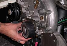
 To figure out pulley spacing we bolted the blower
bracket to the engine then temporality set the head
unit in place. Our point of reference would be the
blower driven pulley.
To figure out pulley spacing we bolted the blower
bracket to the engine then temporality set the head
unit in place. Our point of reference would be the
blower driven pulley. |
| |
|
|
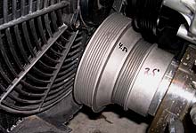
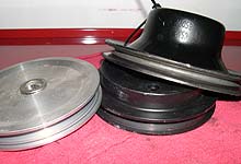
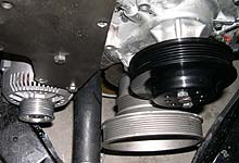
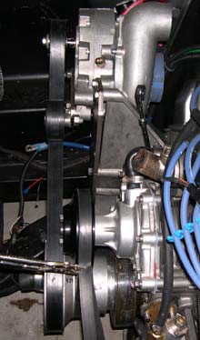
 Next we installed the big crank pulley which has
an outer 8-rib pulley to drive the blower and an
inner 5-rib pulley for the accessories. We had to
clearance the fan shroud and will need to reposition
the fan so the motor does not contact the pulley.
Next we installed the big crank pulley which has
an outer 8-rib pulley to drive the blower and an
inner 5-rib pulley for the accessories. We had to
clearance the fan shroud and will need to reposition
the fan so the motor does not contact the pulley.
|
|
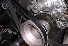
 With the blower belt installed and verified to be
in proper alignment, we worked on alternator and
waterpump pulley spacing.
With the blower belt installed and verified to be
in proper alignment, we worked on alternator and
waterpump pulley spacing. |
| |
|
|
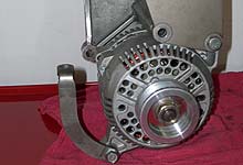
 The alternator location on the Vortech bracket is
designed to work with a smog pump mounted above
the alternator. The L shaped bracket supporting
the bottom of the alternator is intended to bolt
to the underside of the smog pump.
The alternator location on the Vortech bracket is
designed to work with a smog pump mounted above
the alternator. The L shaped bracket supporting
the bottom of the alternator is intended to bolt
to the underside of the smog pump. |
|
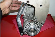
 To make this work we will need to fabricate a
bracket or perhaps use a turnbuckle to support
the alternator and to function as a belt tensioner.
Shown is our initial attempt to use the stock-style
'67 tensioner bracket, however it is slightly
too short.
To make this work we will need to fabricate a
bracket or perhaps use a turnbuckle to support
the alternator and to function as a belt tensioner.
Shown is our initial attempt to use the stock-style
'67 tensioner bracket, however it is slightly
too short. |
| |
|
|
 With the alternator position fixed and in alignment
with the inner crank pulley we are left only with
the waterpump pulley to deal with. We ordered up
an "off the shelf" five rib pulley from
ASP. While the offset is incorrect the fact it is
not custom saves us some money. We can fix the spacing
with shims between the pulley and pump flange.
With the alternator position fixed and in alignment
with the inner crank pulley we are left only with
the waterpump pulley to deal with. We ordered up
an "off the shelf" five rib pulley from
ASP. While the offset is incorrect the fact it is
not custom saves us some money. We can fix the spacing
with shims between the pulley and pump flange.
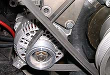
 This alternator location is intended for a 5.0L
engine and pulley configuration. On an early Mustang
it appears we may have to deal with possible belt
rub against the lower radiator hose.
This alternator location is intended for a 5.0L
engine and pulley configuration. On an early Mustang
it appears we may have to deal with possible belt
rub against the lower radiator hose.
|
|
 In order to determine how much offset is required
of the waterpump pulley we mocked up the belt routing.
Then we spaced the waterpump pulley outward on the
pump shaft until the belt alignment appeared correct
between the crank, alternator and waterpump pulleys.
This also gives us a chance to check for interference
issues with the belt and adjacent brackets, pulleys,
or hoses.
In order to determine how much offset is required
of the waterpump pulley we mocked up the belt routing.
Then we spaced the waterpump pulley outward on the
pump shaft until the belt alignment appeared correct
between the crank, alternator and waterpump pulleys.
This also gives us a chance to check for interference
issues with the belt and adjacent brackets, pulleys,
or hoses. |
| |
|
|
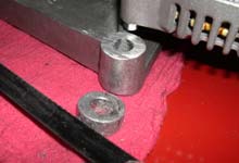
 By cutting off a 1/4" of this mounting boss
on the aluminum blower bracket we can swing the
3G alternator body up higher. This may provide enough
clearance between the belt and hose.
By cutting off a 1/4" of this mounting boss
on the aluminum blower bracket we can swing the
3G alternator body up higher. This may provide enough
clearance between the belt and hose. |
|
 Another bit of customization
will come with the routing of the upper radiator
hose. The blower bracket blocks the path of the
stock '67 hose. By replacing the early thermostat
housing with a late-model unit we should be able
to clear the bracket.
Another bit of customization
will come with the routing of the upper radiator
hose. The blower bracket blocks the path of the
stock '67 hose. By replacing the early thermostat
housing with a late-model unit we should be able
to clear the bracket. |
| |
|
|
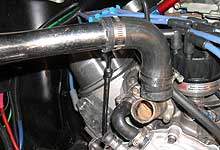
 Another problem for which
we have not yet determined a solution is the tight
space in which to route a 3.5" diameter inlet
hose or pipe. The inlet is partially obstructed
by the valve cover. We believe some crafty welding
of exhaust piping can resolve this issue.
Another problem for which
we have not yet determined a solution is the tight
space in which to route a 3.5" diameter inlet
hose or pipe. The inlet is partially obstructed
by the valve cover. We believe some crafty welding
of exhaust piping can resolve this issue. |
|
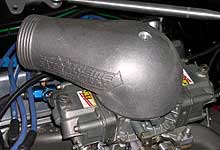
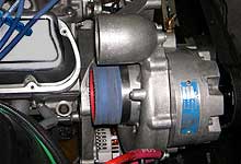
 Getting the compressed air
from the blower into the carburetor has been resolved
via this Extreme Velocity hat from Superior Airflow.
We'll simply fabricate piping between the blower
outlet and the hat from exhaust tubing.
Getting the compressed air
from the blower into the carburetor has been resolved
via this Extreme Velocity hat from Superior Airflow.
We'll simply fabricate piping between the blower
outlet and the hat from exhaust tubing. |
| |
|
|
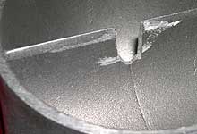
 The carb hat requires a quick
and simple modification to clearance the divider
for the carb stud. This divider is what sets this
hat apart from other bonnet designs, and even carburetor
enclosures. We'll cover this in more detail in an
article coming soon.
The carb hat requires a quick
and simple modification to clearance the divider
for the carb stud. This divider is what sets this
hat apart from other bonnet designs, and even carburetor
enclosures. We'll cover this in more detail in an
article coming soon. |
|
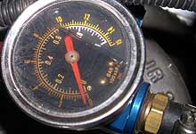
 Another challenge is to figure out the fueling modifications.
Fuel pressure needs to rise proportionally to boost
pressure. The easiest way is to boost-reference
a mechanical fuel pump. Unfortunately, we are running
an electrical pump. We'll have to work this one
out in part II.
Another challenge is to figure out the fueling modifications.
Fuel pressure needs to rise proportionally to boost
pressure. The easiest way is to boost-reference
a mechanical fuel pump. Unfortunately, we are running
an electrical pump. We'll have to work this one
out in part II.  |


