|
Installation
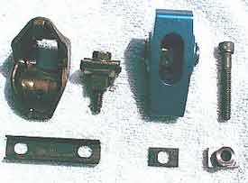 |
| The
stock die-stamped rocker arm (left) and the new Omega
aluminum rocker (right). Stock rockers are notoriously
inaccurate and may vary in ratio with the set. |
We
obtained a good used set of 1.72:1 ratio Omega roller rockers
for about $100. They will yeild a 7.4% increase in lift (from
0.444" to 0.472"). Combined with the reduced friction
of the roller bearing fulcrum and roller tips should free
up some horsepower! As the photo’s show they are a nice
anodized blue color and much beefier (read “stronger”)
than the stock, stamped steel, rockers.
They include bolts and pedestals and are identical to stud
mount rockers EXCEPT for the size of the hole in the trunion-
it is sized to fit the stock pedestal bolts (5/16”) and
not a 3/8” or 7/16” stud, so they cannot be used
in that fashion. Many people have made the mistake of simply
bolting down a set of new pedestal rockers thinking that the
since the architecture is nonadjustable there is no need to
worry about correct rocker arm geometry. This is incorrect.
You MUST check for proper installation and either shim the
pedestals or install longer pushrods to insure proper alignment
and prevent premature valve guide wear! It is actually quite
simple and all you need is a torque wrench. We'll take you
through it...
- To
get to the rockers arms the valve covers need to come off.
On a 5.0L EFI engine this means removing the
upper intake manifold. Start by removing the air inlet tube.
-
Both the throttle cable and transmission TV cable (on auto
equipped cars) simply can be pried loose of the throttle
body. Then remove the two bolts holding the cable bracket
to the throttle body (10mm socket).
- Disconnect
the coolant lines for the EGR spacer behind the throttle
body. Also disconnect the valve-cover to throttle body breather
hose.
- Disconnect
the IAC, TPS and EGR sensor connectors. All of the electrical
connectors have a unique shape so don’t worry about
reconnecting them incorrectly.
- Disconnect
the two small vacuum lines to the EGR valve and the fuel
pressure regulator.
-
Remove the six upper to lower manifold bolts (1/2”
socket w/ 6” extension). Two of the bolts are under
the intake plaque (on a stock intake).
- There
are several vacuum connections underneath the upper manifold
(PCV, brake booster, evap. canister, and AIR valve) that
can be tackled after you get the manifold loose. Then remove
the upper intake assembly from the engine bay.
-
Remove the valve covers. (Cleaning the area around the valve
covers is a good idea before unbolting the valve covers.
Grab that shop vac and clean up in the valleys between the
valve covers and the lower intake. Place a rag over the
lower intake to avoid getting junk into the engine.)
- Unbolt
the stock rockers and remove them from the heads. Clean
all the metal guides that go underneath two adjacent rockers
as it will be reused (at least w/ the Omegas). Once the
old rockers are out it is time to bolt in the new ones.
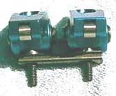
- Pedestal
mount rocker arms have a 5/16" bolt passing down through
the pedestal and into the head. The Omegas are assembled
two rockers at a time placing the pedestals in the stock
guide piece (see photo.) Put a pushrod in place and then
lightly assemble rocker arms on the heads.
-
Start by setting the the #1 piston at top dead center on
the compression stroke. You can confirm this by checking
to see if the rotor is pointing directly at the #1 spark
plug terminal on the distributor cap. If it is not, rotate
the crankshaft until it is. If the distributor is out you
can remove the #1 spark plug, and rotate the engine until
you feel air rushing out of the #1 spark plug hole, indicating
that the #1 piston is coming up on the compression stroke.
Then observe the timing marks on the harmonic damper and
continue rotating the crankshaft until the 0 degree, or
TDC, mark lines up with the pointer. At that point in crankshaft
(and camshaft) rotation, both the intake and exhaust valves
will be closed and the cam will be on the base circle.
- Working
on the #1 piston, slowly spin the pushrod, of the intake
rocker, between two fingers while you tighten the 5/16"
bolt with your other hand. When it becomes difficult to
spin the pushrod, indicating that all clearances have been
taken up, torque the 5/16" bolt to 20 ft-lb. If more
than one full turn of the bolt is required to achieve the
torque setting, you will need to shim the pedestals. Unlike
a stud-mount rocker, the only adjustment possible is adding
or subtracting shims under the pedestal.
 |
| Pedestal
shims. |
Shimming: Back off the bolt, add a .015” - .020”
inch shim under the pedestal, and try it again. Keep adding
shims until the torque applied to the bolt reaches 20 ft-lb
with between one-half and one full turn of the bolt after
the pushrod stops turning. If however the pedestal bolt
reaches 20 ft-lb and the pushrod can still be easily rotated,
the pushrod is too short and must be replaced with a longer
one.
- Repeat
the procedure for the exhaust side. Then move the crank
counterclockwise so that the rotor is pointing at the next
cylinder in the firing order and adjust the rocker arms
for that cylinder. Continue through the firing order until
all rockers are adjusted.
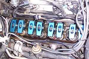
- With
the new rockers bolted down the valve covers and upper intake
were reinstalled with fresh gaskets. Now is a good time
to check and replace any cracked or old vacuum hoses. It
is amazing how many times we hear people blaming a new modification
on drive-ability or performance problems, yet the real problem
was a vacuum leak.
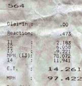
Before |
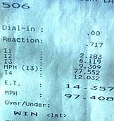
After
 |
Results
Take a look at the time slips and see for yourself. We were
shocked! We ran a 14.261 seconds before the rockers and 14.357
seconds after… In other words the effects of the rockers
were NADA! ZIP! ZILCH! In actuality we lost a little bit.
Both runs were made at Sacramento raceway, about a month apart.
We compared the two timeslips with identical 60ft times to
draw our conclusions. The track conditions on the "before"
pass were much better (cool, dry air) than the "after"
pass, however judging by the same 97.4 mph, we don't think
the weather had a huge effect on the results.
 |
 |
Before
Stock 1.6:1 rockers
Radials
Cool/Dry Air |
After
1.72:1 roller rockers
Radials
Humid/Warmer air temp |
The
horsepower is best represented by the mph and they are within
.014 mph of each other. So, 6 hours of driveway labor, $100
for rockers, $10 for shims and $15 for gaskets. All that and
no increase in power with even a possible slight decrease.
After lots of discussion and debate we have concluded that
with identical weather there may be a small improvement, but
not much. The stock heads increase flow about 15cfm between
.400” and .500” lift, but we are only increasing
the lift by .033” so perhaps the increased lift is not
supported by the heads, or is not enough to overcome the poor
flowing stock intake/exhast ports.
We also suspect that perhaps the stock valve springs are worn
and cannot handle the additional lift. This is an important
point to consider when going to higher ratio rockers, especially
with a high-lift camshaft. You must check for adequate spring
pressure, and ensure there is no coil bind.
Bottom Line
We didn't gain anything by changing to 1.72:1 roller rockers
on our stock 5.0L EFI engine.
Put these rockers on an aftermarket head, or with a different
cam, and you may see an nice increase. If you really want
to optimize your combination, you can even try installing
higher ratio rockers on just the intake or exhaust side (a
common trick for engines with power adders.) The conclusion
is it is one of those modifications that simply must be tested
on your given combination to see if there are any gains in
power. F/M
>
|


