|
Lakewood
Bellhousing Installation
Due to the manufacturing process for the bellhousing, the
centerline of the bellhousing bore may not be aligned with
the centerline of the crank. Lakewood recommends that you
check this alignment and make any corrections if necessary.
Installing a bellhousing that is not centered with the crank
can result in poor shifting, clutch engagement problems, worn
pilot bearing, as well as accelerated wear on the transmission
bearings and gears.
Unfortunately checking the alignment is a major pain in the
neck... literally if you're working with the engine in the
car. The procedure for checking the alignment is to mount
a dial-indicator on the flywheel so that the plunger contacts
the lip of the bellhousing bore. With the bellhousing securely
mounted to the block, rotate the crank 360 degrees and observe
the gauge. The total travel of the needle, divided by two,
is the amount of misalignment between the crank centerline
and the bellhousing bore. Lakewood specifies no more than
0.005" misalignment. Any more than this and you should
correct it using offset alignment dowels in the block or welding
offset washers over the dowel holes in the bellhousing.
Over the course of a week we installed two Lakewood T5 bellhousings,
one in our Project '67 and the other in Jim's '65 coupe, and
both measured within specification (0.004" and 0.003"
respectively). However, due to factors mentioned below, our
initial measurements were way off and we learned quickly that
if you aren't meticulous in how you set up the bellhousing
for measurement you could end up with false readings, which
would lead you to correct a problem that doesn't exist...which
means you would have actually created a misalignment.
Mounting the dial-indicator and stand
The commonly available magnetic stands, with all their arms
and clamps, are bulky and interfere with the bellhousing as
you attempt to rotate the flywheel. We spent a good hour trying
to figure out how to mount the indicator so that it fits in
the bellhousing without interfering with anything. We found
that the best way was to mount the gauge on the stand using
only one of the clamps, as shown in the photo to the right.
We tried using the flexible "snake" type of indicator
stand, but it doesn't bend tight enough, as you can see here
the gauge needs to be at a 90 deg. angle on the stand.
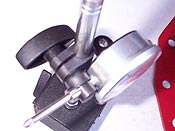
Mounting the dial indicator
as shown worked the best for us. A magnetic base is a
must have. |
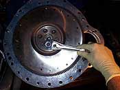
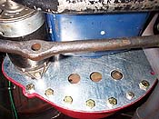
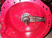
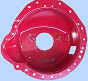
Install the Lakewood block plate,
then the flywheel. Remove two flywheel bolts across from
each other to allow the magnetic indicator stand to sit
square in the center of the flywheel. |
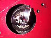
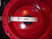
The dial indicator must
contact the lip for the full 360 degrees! You'll need
a small mirror to read the gauge as it turns over. |
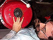
Jim takes a nap after removing
and installing the 30 pound bellhousing for the tenth
time. |
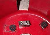
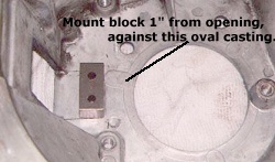
In order for the bellhousing to
contain an explosion the supplied hardware must be installed
in its proper location as listed in the instructions.
|
|
We
found that the best way to mount the magnetic base to the
flywheel is to remove two flywheel bolts directly across from
one another. This allows the base to sit flat on the flywheel
and gives you room to position it as close to the crank centerline
as possible. Be sure to install the Lakewood blockplate behind
the flywheel, and secure the bellhousing with all six bolts
before you measure the alignment! We tried measuring the alignment
without it and found our numbers to be way off.
The most important thing to check for when setting up the
dial-indicator is to ensure the tip makes contact with the
bore lip for the full 360 degrees!
The
bore of the T5 bellhousing turns out to be just about the
same diameter as the length of most dial indicators. Thus
while it may look like the indicator tip is contacting the
lip, it may not be and you'll get false readings. We ran into
this problem at least a half-dozen times. You should watch
the top of the plunger, if it looks bottomed out the other
end is most likely not making contact.
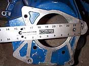
Once the gauge is mounted correctly, set the bezel to zero
and slowly rotate the crank (or have a friend do so.) As you
can see in this photo you wont be able to always read the
gauge as it rotates, so use an inspection mirror. If you rotate
the crank and find that you're getting high-readings through
half the travel, then the indicator goes back to zero for
the remaining 180 degrees, it means the indicator is not contacting
the lip. We'd see as much as .030" runout at the halfway
point, then the indicator would come back to zero. The activity
of the indicator needle should emulate a mirror image, where
for example, you get 0.010" travel above zero and 0.010"
below zero. In this example the total travel would be 0.020",
divided by two, indicats 0.010" misalignment.
Measure
until you get repeatable results
On our first attempts we were seeing numbers all across
the board, from 0.010" to as much as 0.040". We
found that if you only installed two of the six bellhousing
bolts, while it may seem secure, the bellhousing is not flush
with the block, which gives a false misalignment. We recommend
that when measuring alignment you install both the bellhousing
and blockplate and use all six bellhousing bolts, torqued
properly. Also make sure the dowels in the block and mating
surfaces are clean and free of any crud or paint. Once we
went through these precautions the runout for both our bellhousings
were within specifications. We removed the bellhousing and
remounted it three more times to ensure we could reproduce
the same reading each time. Only then can you be confident
you have an accurate measurement. If you are not sure and
you install corrective dowels, you may make the problem worse.
Correcting misalignment
 |
 |
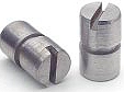
| Offset dowels (top)
and weld-on washers available from Lakewood. |
If
you have between 0.005" - 0.025" misalignment, you
can correct it with either offset dowels or welding on washers
over the dowel holes in the bellhousing itself. The offset
dowels come in 0.007", 0.014" and 0.021" offsets.
Insert them in the block, and use a screwdriver to 'clock'
them in the right spot. You'll need to measure again to make
sure you're within spec.
If you're bellhousing requires more offset than this to correct
the problem, or you want a permanent fix (the dowels need
to clocked every time you remove the bellhousing) you can
weld on alignment washers over the dowel holes in the bellhousing.
However we would be very skeptical of any misalignment over
0.020", this would indicate to us that perhaps the measurement
is incorrect or there is a problem with the block or bellhousing.
Before welding any washers we'd advise that you obtain another
Lakewood bellhousing and recheck, or check your bellhousing
on another block. To weld the washers you'll have to slightly
enlarge the dowel holes in the bellhousing, then bolt the
bellhousing to the block using the supplied longer dowels.
Take a measurement, then carefully tap the bellhousing into
position with a mallet, re-measure, and do this until it is
centered. Finally torque the bolts, re-measure to make sure
you didn't disrupt the alignment, then slip the washers over
the dowels an weld them in place.
Other
Modifications
Because of the larger than stock size of all Lakewood
bellhousings, it is inevitable that you will have some sort
of clearance problem, be it with headers, clutch linkage,
exhaust, etc. The solution for most of these interference
problems is to grind material off the bellhousing to gain
the needed space. Technically the manufacturer, the
NHRA and SFI consider any modifications as voiding the SFI
certification. However the reality is very few cars can fit
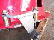
a larger bellhousing without slight modification. We had to
drill two holes to mount our clutch fork fulcrum because we're
using the early style mechanical clutch linkage. The Lakewood
T5 bellhousing is set up for the cable clutch mechanism.
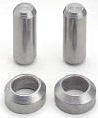
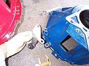
In addition, because the 302 in Project '67 is a 1990 block,
there is no mouting location for the block pivot for the early
style clutch equalizer bar. Windsor-Fox Performance sells
an adapter designed to allow early mechanical linkage to work
with newer blocks, but it is setup for the stock bellhousing.
We had to adapt it to the Lakewood which required some clearancing
of the flange and also cutting some standoff spacers as seen
in the photos below.
|


