Early
Mustang Rack and Pinion Conversion
(cont.) |
12
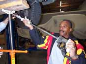
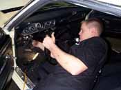
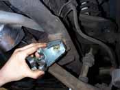
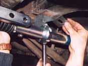
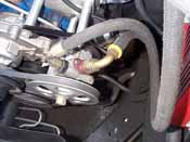
As you can see, the shaft and box come out at a severe
angle. We had the luxury of a lift, but with the car on
jackstands you may have some trouble. You may want to
pull the cover off the steering box and work on separating
the shaft from the box. |
 13
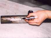
The only cutting required for this project is to trim
the steering column tube back 5 9/16". Measure from
the end of the column and cut the column straight. Use
a file to clean off any burrs.
13
The only cutting required for this project is to trim
the steering column tube back 5 9/16". Measure from
the end of the column and cut the column straight. Use
a file to clean off any burrs. |
14
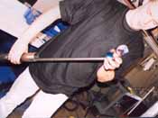
Install the steering shaft and the new bearing assembly
(provided) into the tube. Long shaft cars reuse the stock
shaft, shown here.
|
 15
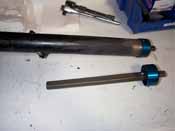
Cars with half shafts will use a new slipshaft provided
with the kit.
15
Cars with half shafts will use a new slipshaft provided
with the kit. |

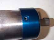
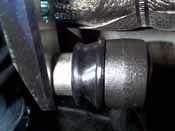
16
Tap the bearing assembly so that is is seated against
the column tube. Drill two 9/64" holes through the
bearing retainer and column. |
17
Remove the bearing assembly and clean out any drill shavings
which may have fallen into the tube...
|
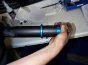
18
Reassemble the column by first sliding the column support
sleeve onto the tube, then the bearing assembly. Fasten
the bearing retainer to the tube with two sheetmetal screws.
|
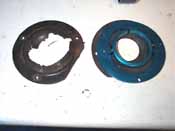 19
Shown here is the new column support. The inner ring is
slips onto the column tube (prev. picture) and the outer
ring attaches to the firewall. If your column to firewall
seal looks the one on the left, replace it with a new
one. They are available from most Mustang mail order houses
19
Shown here is the new column support. The inner ring is
slips onto the column tube (prev. picture) and the outer
ring attaches to the firewall. If your column to firewall
seal looks the one on the left, replace it with a new
one. They are available from most Mustang mail order houses |
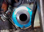
20 Column
support outer ring, and new seal, attached to firewall
from underneath the dash. Reuse the sheetmetal screws
from the stock support collar. |
21
The column can now be placed back into the car. Be sure
to replace the upper column bearing and spring before
torquing down the steering wheel nut (50 lb.ft.) |
22
Adjust the column to its original height, and reattach
the underdash bracket and wiring harness.. Line up the
column support ring and tighten up the the set-screws.
Shown is the modified column, as it appears in the engine
compartment.
|
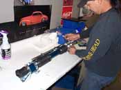
23 The
rack ships assembled. To prepare for installation, disassemble
the inner and outer brackets by removing the allen head
screws. |
24
Remove the lower control arm bolts and install the inner
brackets using the new hardware provided. Install them
loose for now. On '65-'66 cars use the spacer provided
to properly align the brackets with the rack and pinion
tube. On '67 and later Mustangs replace the eccentric
washer with the square eccentric eliminator plates provided.
This will result in a more stable alignment setting. Note
that the mounting tabs face towards the wheels.
|
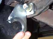
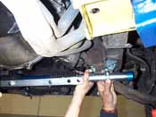
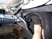
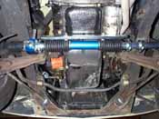
25
The outer frame brackets install in the mounting locations
previously used for the stock crossmember. Loosely install
the right (passenger) side frame bracket first. |
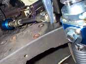
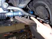
26
Loosely install the rack and pinion assembly to the right
side frame bracket. The left side will be secured after
the intermediate shaft assembly is put into place. |
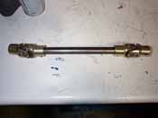
27
Shown here is the intermediate shaft assembly which connects
the steering shaft to the rack. |
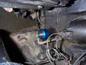
28
Attach the intermediate shaft assembly to the end of the
steering column shaft and torque the allen screws to 15-17
lb.ft. Raise up the left side of the rack and install
the lower u-joint onto the splined input shaft of the
rack and pinion assembly. Now the left side outer bracket
can be installed.
|
29
Install the inner bracket clamps. Tighten all the brackets
and clamps in an even manner to prevent distorting the
rack tube, or stripping the bracket threads. Torque the
outer frame brackets and inner control arm brackets to
75 lb.ft. Torque the allen screws on the clamps to 15-17
lb.ft. |
30
Remove the center link and attach the inner tie rods,
using the tapered bushings pictured below. Torque the
castle nuts to 35 lb.ft and be sure to insert the cotter
pins. Bend the cotter pins towards the tires so they don't
puncture the rack boots. The centerlink can now be reattached
to the rack, torque the nuts to 75 lb.ft.
|
31 Total
Control provides the tapered inner tie-rod bushings. If
you have Granada front brakes and are using Granada tie
rods, Total Control can provide the correct bushing. |
32
The final step is to attach the outer tie rods and adjustment
sleeves. The clamps on the sleeves must face towards the
rear of the car so they do not bind against the rack. |
33
This car is a manual so we are done. However if you were
installing a power rack, the pump and hose connections
would be the final steps. |
|
34
Before lowering the car down, double check all the connections
and check for any binding or interference. The final
step is to have the front end aligned. Total Control
suggests the following settings depending on street
or track driving:
|
| |
Street
|
Track |
| Neg.
Camber: |
0-1/2 deg.
|
1-2
deg. |
| Pos.
Camber: |
1-1
1/2 deg. |
1-1
1/2 deg. |
| Toe
in |
1/16"-1/8" |
1/32"-1/8" |
Total
Control Products
9901 Kent Street
Suite 1
Elk Grove, CA 95264
1-888-685-1790
|


